Eureka AIR delivers breakthrough ideas for toughest innovation challenges, trusted by R&D personnel around the world.

A double-ended traveling wave ranging method based on the arrival time difference of the starting point of the fault waveform

A double-ended traveling wave, fault location technology, applied in the fault location, measuring electricity, measuring device and other directions, can solve the problem of low positioning accuracy of the frequency response bandwidth of the traveling wave sensor, and achieve the effect of reducing the positioning accuracy

Active Publication Date: 2020-02-21
WUHAN SUNSHINE POWER SCI & TECH
View PDF6 Cites 0 Cited by
  • Summary
  • Abstract
  • Description
  • Claims
  • Application Information

AI Technical Summary

Problems solved by technology

[0004] The purpose of the present invention is to obtain the time of arrival of the traveling wave by capturing the wave head to obtain the time of arrival of the traveling wave or using the method of wavelet analysis to obtain the singular point of the signal for the traditional double-terminal traveling wave fault ranging to obtain the time of arrival of the traveling wave. Due to the fact that the frequency response bandwidth is greatly affected and the positioning accuracy is not high, a double-terminal traveling wave ranging method based on the time difference of arrival at the starting point of the fault waveform is proposed to effectively reduce the influence of external factors such as dispersion and further improve positioning accuracy.

Method used


Image

  • A double-ended traveling wave ranging method based on the arrival time difference of the starting point of the fault waveform
  • A double-ended traveling wave ranging method based on the arrival time difference of the starting point of the fault waveform
  • A double-ended traveling wave ranging method based on the arrival time difference of the starting point of the fault waveform

Examples


Embodiment 1

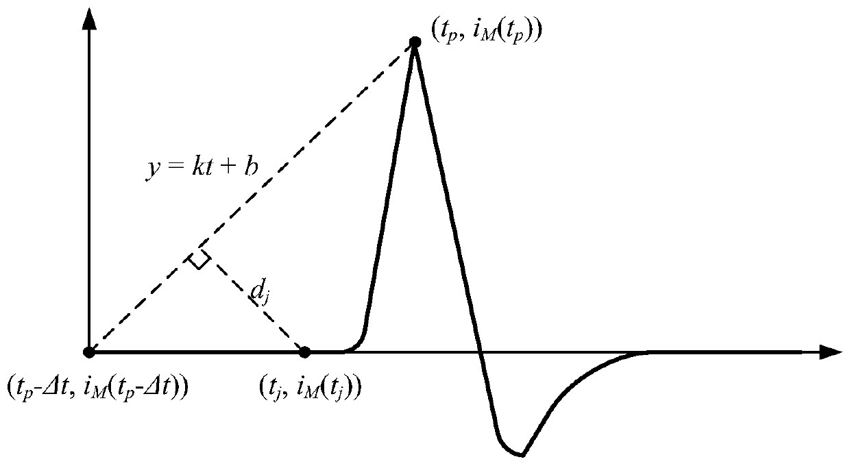
[0052] According to the aforementioned principle of double-terminal traveling wave fault location and the principle of calculating the starting point of the fault traveling wave waveform, a method of double-terminal traveling wave fault location based on the time difference of arrival at the starting point of the waveform is obtained, including the following steps:

[0053] S31: Obtain the traveling wave waveform data of the M-terminal and N-terminal of the transmission line and perform zero-phase-shift digital filtering processing to obtain i M (t), i N (t);

[0054] S32: calculate i M (t), i N (t) The waveform points corresponding to the maximum absolute value are (t p ,i M (t p )), (t q ,i N (t q ));

[0055] S33: Set the time coordinate axis offset parameter △t, and calculate i M (t), i N The reference points when the waveform starting point of (t) has not yet reached are (t p -△t,i M (t p -△t)), (t q -△t,i N (t q -△t));

[0056] S34: connect(t p -△t,i ...

Embodiment 2

[0065] In the step S31 of embodiment 1, the method that the traveling wave waveform data is carried out zero phase shift digital filtering comprises the following steps:

[0066] Step S41: reverse the sequence s(n) formed by the acquired traveling wave waveform data in the time domain to obtain:

[0067] u(n)=s(K-1-n)

[0068] Among them, s(n)={s(0),s(1),…,s(K-1)}, n=0,1,2,…,K-1 is a discrete signal, K is s(n ), u(n) is the sequence of s(n) flipped in the time domain;

[0069] Step S42: Perform low-pass filtering on the sequence u(n), and use the unit impulse response sequence to perform convolution with the sequence u(n):

[0070] v(a)=u(n)*h(m)

[0071] Among them, v(a) is the low-pass filtered sequence of u(n), h(m) is the unit impulse response sequence, a=0,1,2,...,K+f-2, m=0,1 ,2,...,f-1, f is the number of points in the unit impulse response sequence h(m);

[0072] Step S43: reverse the sequence v(a) obtained in step S42 in the time domain:

[0073] w(a)=v(K+f-1-a)...

Embodiment 3

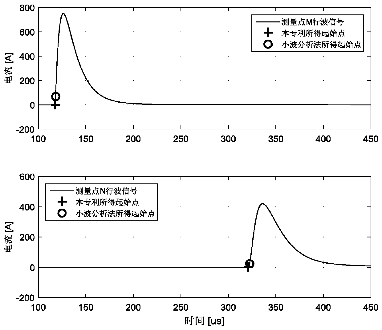
[0083] In order to show the influence of this method on eliminating dispersion and other factors more intuitively, the fault distance measurement of cable transmission line is simulated by using PSCAD software, and the present invention is compared with the traditional traveling wave distance measurement method based on wavelet analysis algorithm.

[0084] The simulation model is that the transmission line adopts a three-core XLPE cable with a total length of 50 kilometers. At a distance of 40 kilometers to the left of point N (or 10 kilometers to the right of point M), the core wire of phase A is injected based on a double-exponential model. The traveling wave pulse, as the point of failure. The traveling wave data is monitored at both ends of M and N, and the traveling wave ranging simulation waveform diagram of the traveling wave starting point is obtained by using the present invention and the wavelet analysis method respectively. image 3 shown.

[0085] Calculated accor...


PUM


Abstract

The invention provides a double-end traveling wave distance measuring method based on fault waveform initial point step-out time. The double-end traveling wave distance measuring method based on faultwaveform initial point step-out time comprises the following steps: carrying out zero-phase-shift digital filtering on traveling waveform data; establishing a linear equation by selecting a referencepoint when a waveform initial point has not arrived yet and a waveform maximum value; calculating to obtain a point of various waveform points, which is distant from the straight line by the longestdistance, between two points as a traveling waveform initial point; and calculating the position of a fault point according to a double-end traveling wave fault distance measuring principle. Comparedwith a traditional double-end traveling wave fault distance measuring method which acquires traveling wave arriving time by using a wave capturing head or acquiring signal fantastic points by using wavelets to obtain traveling wave arriving time and the like, the method for calculating the traveling wave step-out time is not affected by a traveling wave dispersion dispersion effect, and the circumstance that positioning precision is reduced due to traveling wave attenuation and distortion problems caused by wave impedance is avoided; and meanwhile, the problem that the positioning precision ofa fault point is not high due to distortion of a traveling wave head caused by the reason that the frequency response bandwidth of a traveling wave sensor is narrow can be solved.

Description

technical field [0001] The invention relates to the technical field of transmission line fault location, in particular to a double-terminal traveling wave ranging method based on the time difference of arrival at the starting point of a fault waveform. Background technique [0002] In the place with the highest fault occurrence rate in the high-voltage transmission network, the rapid and accurate location of the fault point can greatly shorten the repair time of the fault line and reduce the loss caused by power failure, which has great social and economic benefits. The transient traveling wave signal is generated after the short circuit fault of the transmission line, and the accurate time when the fault traveling wave head reaches the measurement point on the line is determined by comprehensive analysis of the traveling wave voltage and traveling wave current sampling value after the fault occurs, which can be used to realize Fault location. For the wave process of transm...

Claims


Application Information

Patent Timeline
Patent Type & Authority Patents(China)
IPC IPC(8): G01R31/08
CPCG01R31/088
Inventor 钱冠军陈继东张猛赵纯胡枫余刚华张国清
Owner WUHAN SUNSHINE POWER SCI & TECH
Why Eureka
Eureka Blog
Learn More