Rearview device and vehicle with such rearview device

a rearview device and rearview technology, applied in the field of external rearview devices, can solve the problems of not always being produced from parts, and it is difficult to guide light from such light emitting diodes to another location, and achieve the effect of reducing the aerodynamic resistance of the vehicle and being easy to moun

Active Publication Date: 2022-04-19
SMR PATENTS S A R L
View PDF13 Cites 0 Cited by
  • Summary
  • Abstract
  • Description
  • Claims
  • Application Information

AI Technical Summary

Benefits of technology

[0036]Thus, the rearview device may include a housing in which at least one light producing device is arranged. The housing includes an at least partially transparent element that provides a contact surface facing to an interior side of said housing and an outer exit surface facing to the outside of said housing. “Transparent” means that for at least some of the wavelengths in the visible light frequency range, the light that enters the element also exits the element. “At least partially transparent” means that not necessarily, the entire element is transparent; it may have some opaque portions as well, e.g., at the edges. Adjacent to the contact surface of the at least partially transparent element, a part of the light producing device having a surface via which light exits the light producing device is arranged in such a manner that the exiting light is guided through the at least partially transparent element to the outer exit surface. Hence, all light producing elements can be arranged in the interior of the housing, and since an element of the housing itself is transparent or has at least transparent portions, no further elements need to be provided at the outside. Each car producing company can design an individual rearview device for each kind of vehicle, and it is only the transparent element as part of the housing which may need to be tailor-shaped for the rearview device's design. The remainder of the optical elements can be always of the same type. Higher numbers of such elements can be produced, which leads to lower overall costs.
[0054]A first light producing device includes a printed circuit board on which a light source, preferably a light emitting diode, is mounted, and the printed circuit board is held in a body having at least one transparent portion that provides (or presents) an exit surface via which light emitted from said light source can exit the light producing device. Hence, the light producing device can be produced as a very compact component, usable in different kinds of rearview devices.

Problems solved by technology

However, side turn indicator units need to be visible from the exterior and can thus not always be produced from parts that fit into vehicles of different design.
In both of these cases, water can enter into the housing, causing humidity therein, which can be detrimental to the durability of the electrical equipment therein, namely of the light emitting diode itself.
It is, however, difficult to guide light from such light emitting diode to another location.

Method used


Image

  • Rearview device and vehicle with such rearview device
  • Rearview device and vehicle with such rearview device
  • Rearview device and vehicle with such rearview device

Examples


first embodiment

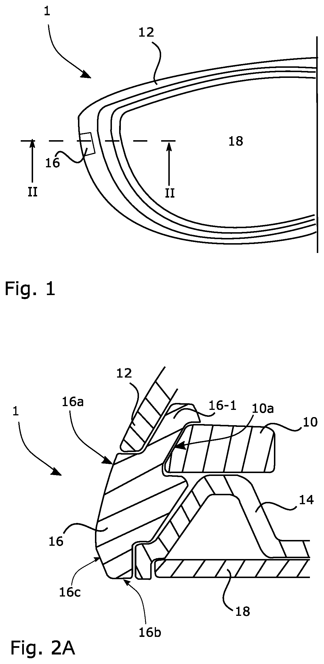
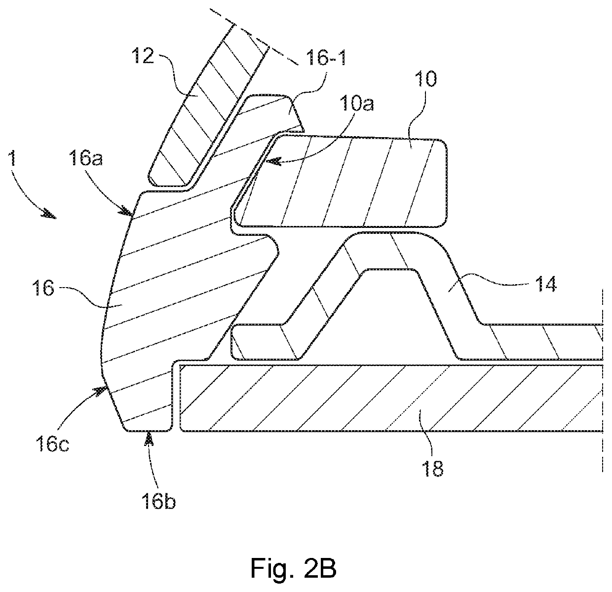
[0075]FIG. 1 depicts a rearview mirror indicated at 1, being a rearview device according to a The rearview mirror 1 comprises a light producing device 10, arranged within a housing being made up of a hollow shell or casing a wall 12 of which is shown in the sectional view of FIG. 2A or FIG. 2B. In the example of FIG. 2A, part of the housing is also a bezel 14, in a known manner, wherein a transparent lens-like element 16 is arranged between the wall 12 and the bezel 14, to complement these two parts when forming the overall housing, preferably in manner for the housing to be tight. For instance, the transparent element 16 can be clamped between the wall 12 and the bezel 14. The transparent element 16 can be formed out of glass, or produced by moulding transparent plastic material, and in all examples herein is fully transparent, but could as well be only portion-wise transparent as long as its function explained hereinafter is fulfilled.

[0076]In the example of FIG. 1 with the cross...
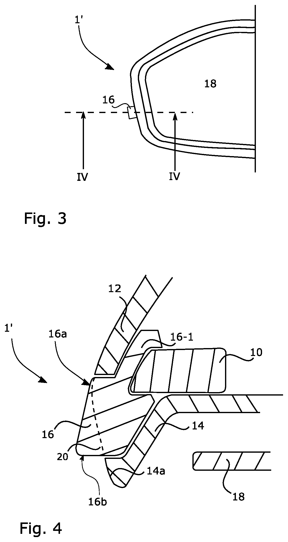
second embodiment

[0082]In both rearview mirrors 1 and 1′, the first as well as the second embodiment, the light producing device 10 is provided as a compact entity or unit and, thus, in form of a module as depicted in FIG. 5. At the heart thereof is a printed circuit board 22 that bears at least one light emitting device (LED) 24. The printed circuit board 22 is held in a lower half 26 of the light producing device 10 that is covered by an entirely transparent upper half (cover) 28. Ports 30 enable the supply of electrical energy to the printed circuit board 22. The printed circuit board 22 includes all elements necessary for controlling the LED 24, like a control unit and impedance matching elements (not shown). The LED 24 is suited for being intermittently operated (flashing) under such control, in order to provide a side turn indicator unit of the rearview mirror 1, 1′. Instead of using separable halves 26, 28, the printed circuit board 22 can be integral with the remainder of the body, such as c...

fourth embodiment

[0083]FIGS. 6 and 9 show alternative light producing devices 40 to be used with a third and fourth embodiment of a rearview device 101′, 101″. Each one of said alternative light producing devices 40 is more or less bullet shaped. In both alternatives the light producing devices 40 are provided with at least one optical fibre 48 for guiding light emitted from a not shown LED to a pin 44 that terminates in a dome-shaped end portion 42. Fixing means 46 e.g. in form of clamping arms are optional.

[0084]FIG. 7 depicts the third embodiment incorporating a fixed mirror solution. The housing of the rearviewdevice 101′ according to FIG. 7 makes usage of the elements 12, 14 already described with respect to FIG. 2. But the transparent element 16 of the third embodiment differs from the one shown in FIG. 2, by providing a cavity for accommodating the dome-shaped end portion 42 of the light producing device 40.


PUM


Abstract

An external rearview device for a motor vehicle includes a housing, and one or more of at least one light emitting or a receiving device, including one or more of at least one light producing device or at least one camera device arranged within the housing, and at least one at least partially transparent element closing an opening provided by the housing, the at least partially transparent element being provided in form of a first module attached to the housing, and the one or more of the light producing device or the camera device being provided in form of a second module attached to the first module, the first module and the second module being mechanically releaseably coupled.

Description

CROSS-REFERENCE TO RELATED APPLICATIONS[0001]This application is a continuation-in-part of International Patent Application No. PCT / EP2018 / 071371, filed Aug. 7, 2018, which claims the benefit of foreign priority to German Patent Application No. DE 10 2017 119 542.4, filed Aug. 25, 2017, each of which is hereby incorporated by reference in its entirety for all purposes.BACKGROUND1. Field of the Invention[0002]The present disclosure relates to an external rearview device, in particular for a motor vehicle, including a housing, and at least one light emitting and / or receiving device, including at least one light producing device and / or at least one camera device arranged within said housing, and at least one at least partially transparent element closing an opening provided by said housing. Such rearview devices which are externally coupled to a vehicle body commonly include a reflective element to provide a rearview mirror element and / or a camera to provide an optical rearview apparat...

Claims


Application Information

Patent Timeline
Patent Type & Authority Patents(United States)
IPC IPC(8): B60R1/12F21S43/237F21S43/249F21S43/14F21S43/19F21S43/245B60Q1/26F21S43/27B60Q9/00
CPCB60R1/1207B60Q1/2665F21S43/14F21S43/19F21S43/237F21S43/245F21S43/249B60Q9/005F21S43/27
Inventor HORNE, STEVELETTIS, ANDREWREHILL, GRAHAMHERRMANN, ANDREAS
Owner SMR PATENTS S A R L
Why Eureka
Try Eureka