
Articulated element between the light source carrier frame and the leveling motor in a headlight of a motor vehicle

a technology of articulation element and light source carrier frame, which is applied in the direction of optical signalling, transportation and packaging, light and heating apparatus, etc., can solve the problem of negative impact on the functioning and lifetime of the leveling motor, the component of the radial force perpendicular to the hollow cylinder axis is not sufficiently eliminated, and the drive shaft and the carrier frame are exposed to undesirable tension in the radial direction

Active Publication Date: 2022-04-26
HELLA SATURNUS SLOVENIJA DOO
View PDF20 Cites 0 Cited by
  • Summary
  • Abstract
  • Description
  • Claims
  • Application Information

AI Technical Summary

Benefits of technology

[0001]The invention relates to an articulated element which is used for the force transmission between the light source carrier frame and the leveling motor in order to regulate the angle of the light beam of a headlight in a motor vehicle. The light source carrier frame with one or several light sources is pivotally mounted to the headlight housing that is later on fixed to the car structure. The leveling motor with a drive shaft is fixed to the headlight housing and can push the drive shaft in or out in a primarily linear direction. The leveling motor is used to drive said carrier frame, i.e. to pivot said carrier frame around the carrier frame axis for a certain angle, thereby changing the angle of a light beam for that angle. For example, the direction of the light source beam is, due to the carrier frame rotation, directed downwards, so the light does not disturb the driver who is approaching.
[0008]Given the fact that the drive shaft with the head can move only in linear direction along its axis (the drive shaft does not move in radial directions), in order to minimize the radial force as much as possible, preferably to eliminate the radial force acting on the drive shaft, when the carrier frame pivots around the carrier frame axis, an articulated element had to be introduced between the drive shaft and the carrier frame. This means that the construction of the articulated element enables the split of previously one connection point between the drive shaft and the carrier frame into two connection points, namely a first connection point between one side of the articulated element and the drive shaft and a second connection point between the other side of the articulated element and the carrier frame. The articulated element enables the displacement movement of the first connection point relative to the second connection point in all radial directions relative to the drive shaft axis thereby eliminating or minimizing any radial force on the drive shaft.
[0010]The connecting element due to its flexibility allows pivotal movement of the hollow cylinder relative to the bayonet base. The plane on which the hollow cylinder moves relative to the bayonet base is essentially perpendicular to the hollow cylinder axis.

Problems solved by technology

If the drive shaft was directly connected to the carrier frame without any articulated element and the leveling motor drive shaft moves linearly from its nominal position, the drive shaft and the carrier frame would be exposed to undesirable tension in radial direction due to said difference between the linear movement of the drive shaft and the rotational movement of the carrier frame.
Thus when the linear movement of the drive shaft is translated into the rotational movement of the carrier frame around the carrier frame axis, the drive shaft is exposed to radial force which has negative impact on the functioning and lifetime of the leveling motor, because the producers of leveling motors guarantee their proper functioning only up to a certain amount of radial force.
However, the component of the radial force in the hollow cylinder axis direction is practically eliminated due to the sliding of the hollow cylinder along its axis, whereas the component of the radial force perpendicular to the hollow cylinder axis is not sufficiently eliminated.
As a result, the undesirable radial force in this direction is still present, therefore, the performance of the leveling motor is deteriorated and its lifetime is shortened.

Method used


Image

  • Articulated element between the light source carrier frame and the leveling motor in a headlight of a motor vehicle
  • Articulated element between the light source carrier frame and the leveling motor in a headlight of a motor vehicle
  • Articulated element between the light source carrier frame and the leveling motor in a headlight of a motor vehicle

Examples


Embodiment Construction

[0012]It is an object of the present invention to provide an improved solution for the articulated element which overcomes the above mentioned problems.

[0013]The articulated element according to the invention is further described below and presented in figures:

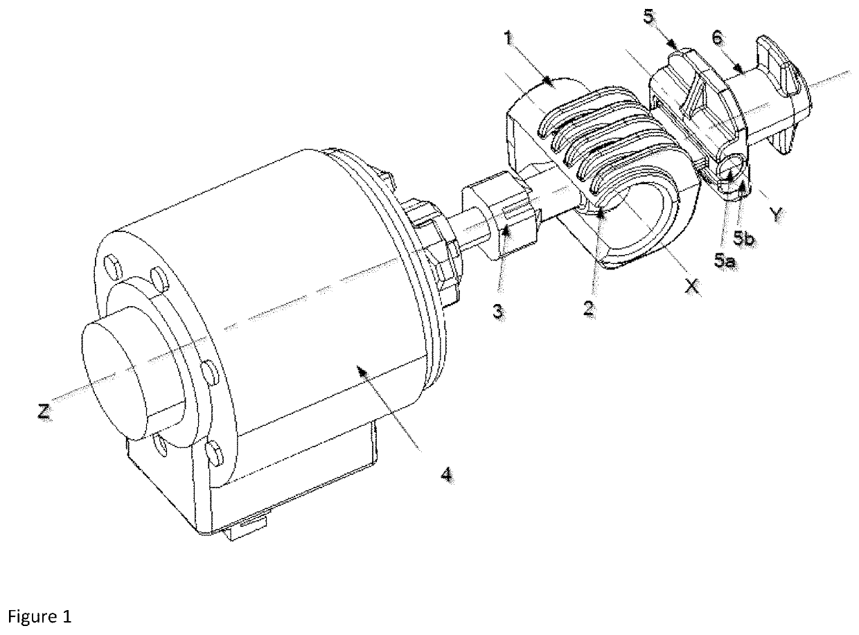
[0014]FIG. 1 presents the neutral position of the articulated element connected to the leveling motor

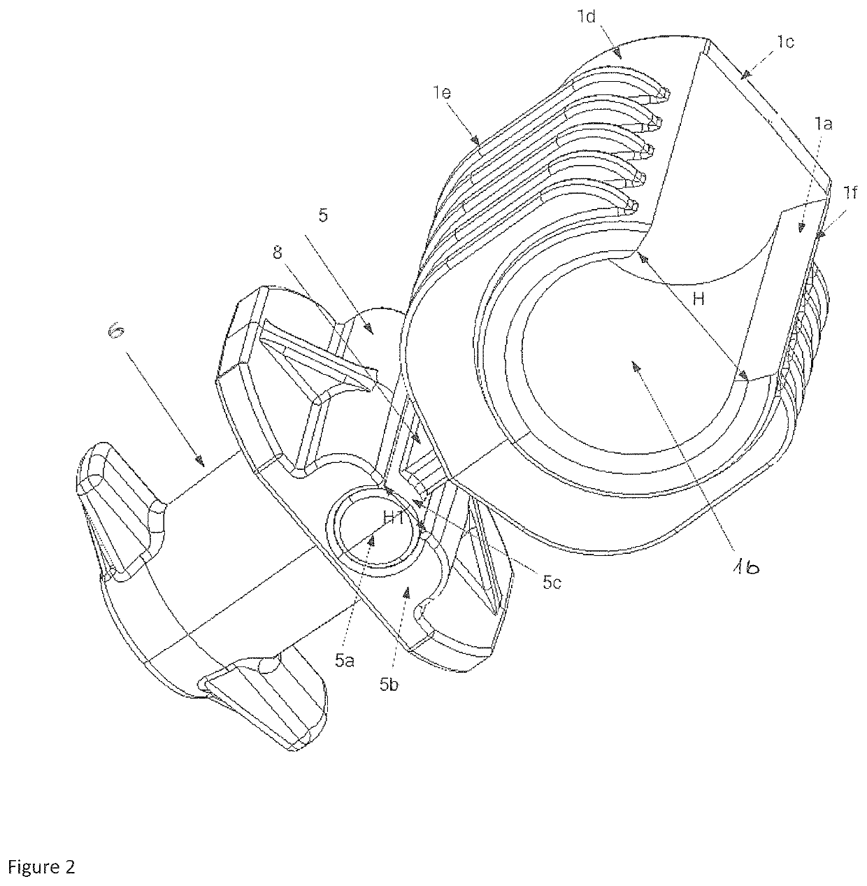
[0015]FIG. 2 presents the articulated element

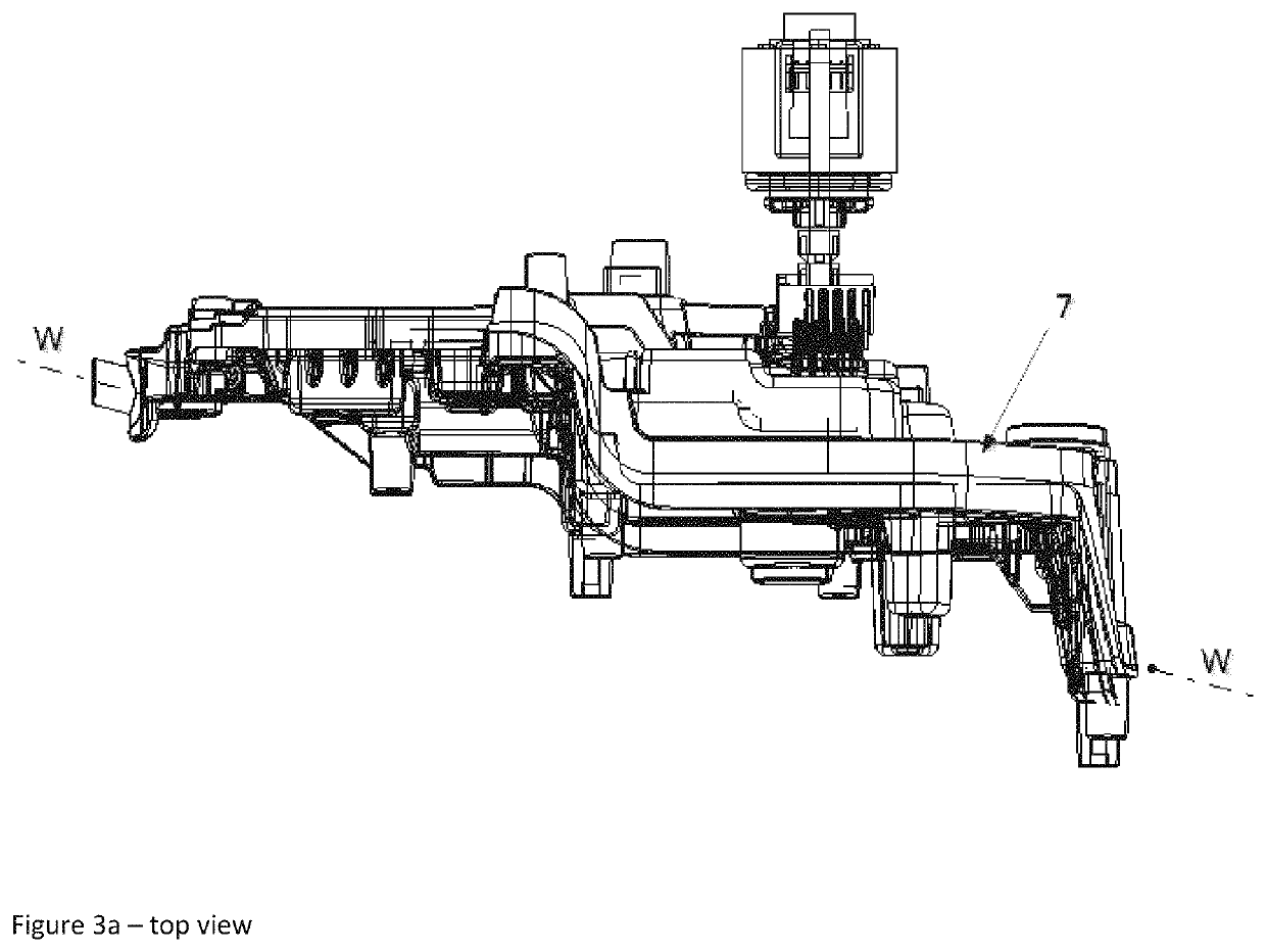
[0016]FIGS. 3a and 3b present the position of the articulated element when the drive shaft of a leveling motor is moved in linear direction backward (top view and side view)

[0017]FIG. 4 presents the adjustment range defined by the movement of the hollow cylinder relative to the head of the drive shaft.

[0018]Articulated element between the light source carrier frame and the leveling motor in a headlight of a motor vehicle according to the invention, which is presented in FIGS. 1 to 4, comprises:[0019]a hollow cylinder 1 with a cylinder axis X, whereby said hollow cylinder 1 is adapted...


PUM


Abstract

The invention relates to an articulated element between a light source carrier frame and a leveling motor in a headlight of a motor vehicle, which is used to transform the linear movement of the drive shaft of the leveling motor into the rotation of the carrier frame for a certain angle. The light source carrier frame with one or several light sources is pivotally mounted to the headlight housing that is later on fixed to the car structure. The leveling motor with a drive shaft is fixed to the headlight housing, and can push its drive shaft in or out in a primarily linear direction. Undesirable radial force acting on the drive shaft are minimized or eliminated by the use of the articulated element according to the invention. The articulated element comprises a hollow cylinder adapted for insertion of a head fixedly attached to the drive shaft of the leveling motor and a hinge which consists of a first hinge element, which is fixedly attached to the hollow cylinder, and of a second hinge element, which is fixedly attached to a bayonet base or is formed as a uniform part of the carrier frame and whereby the cylinder axis is essentially parallel to the hinge axis. The horizontal component of the radial force onto the drive shaft is eliminated by allowing the hollow cylinder to slide along its axis relative to the drive shaft. At the same time the hinge in combination with the hollow cylinder pivoting around the head minimizes radial force on the drive shaft in vertical direction.

Description

[0001]The invention relates to an articulated element which is used for the force transmission between the light source carrier frame and the leveling motor in order to regulate the angle of the light beam of a headlight in a motor vehicle. The light source carrier frame with one or several light sources is pivotally mounted to the headlight housing that is later on fixed to the car structure. The leveling motor with a drive shaft is fixed to the headlight housing and can push the drive shaft in or out in a primarily linear direction. The leveling motor is used to drive said carrier frame, i.e. to pivot said carrier frame around the carrier frame axis for a certain angle, thereby changing the angle of a light beam for that angle. For example, the direction of the light source beam is, due to the carrier frame rotation, directed downwards, so the light does not disturb the driver who is approaching.[0002]The connection point of the drive shaft to the carrier frame is above or below t...

Claims


Application Information

Patent Timeline
Patent Type & Authority Patents(United States)
IPC IPC(8): B60Q1/076B60Q1/068
CPCB60Q1/076B60Q1/0683B60Q2200/32F21S41/657F21V17/107F21V14/02F21W2102/13
Inventor STEGOVEC, EDWIN
Owner HELLA SATURNUS SLOVENIJA DOO
Learn More