Fluid powered motor

a technology of motors and fluids, applied in mechanical equipment, engines with rotating cylinders, belts/chains/gearings, etc., can solve problems such as contamination of food products being processed/handled

Inactive Publication Date: 2012-03-13
HYDRODRIVES TECH
View PDF12 Cites 0 Cited by
  • Summary
  • Abstract
  • Description
  • Claims
  • Application Information

AI Technical Summary

Benefits of technology

[0016]Thus, the higher fluid pressure applied to the pistons moving from crest to troughs produces a torque and hence rotation of the cylinder block, valve plate, and the output shaft.
[0018]As the motor in accordance with the invention is designed to operate at comparatively low hydraulic pressures, low cost, light weight, corrosion resistant plastics may be extensively used in manufacture.
[0027]The efficiency of the motor is enhanced by minimising unbalanced radial forces acting on the cylinder block by the selection of the appropriate ratio of the number of cam lobes to number pistons forming the assembly.
[0049]Each of the ports is alternatively linked to one, and then the other, channel. This arrangement allows the motor to operate in both directions of rotation by simply switching the pressure feed and return lines, or reversing the flow of fluid e.g. water through the motor.

Problems solved by technology

Sometimes, operatives omit to remove covers resulting in overheating, and possibly contamination of the food product being processed / handled.

Method used


Image

  • Fluid powered motor
  • Fluid powered motor
  • Fluid powered motor

Examples


Embodiment Construction

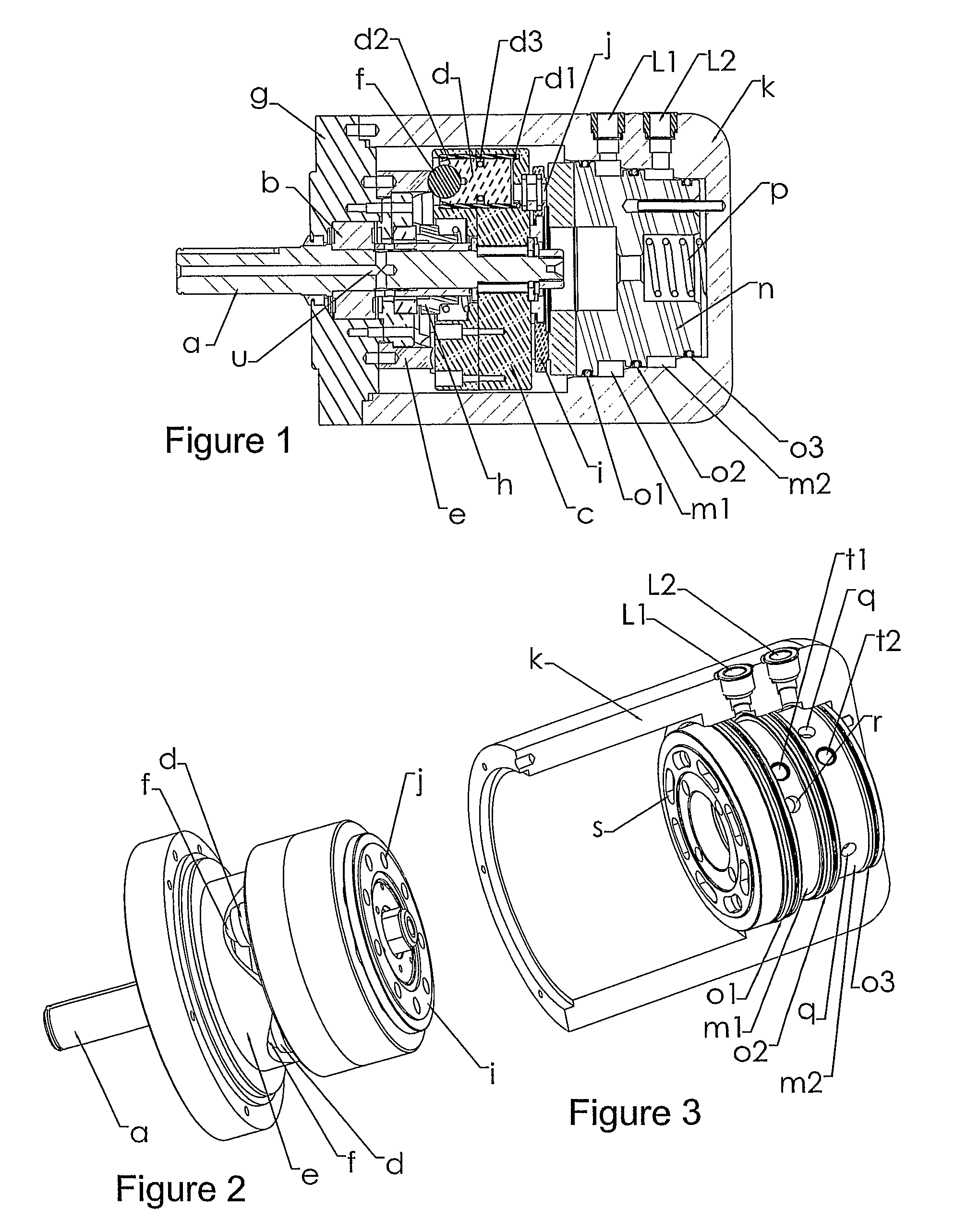
[0068]Like reference numerals are used for like components in all Figures.

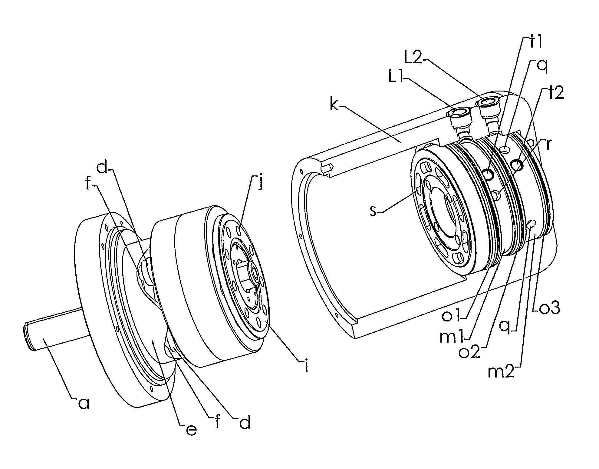
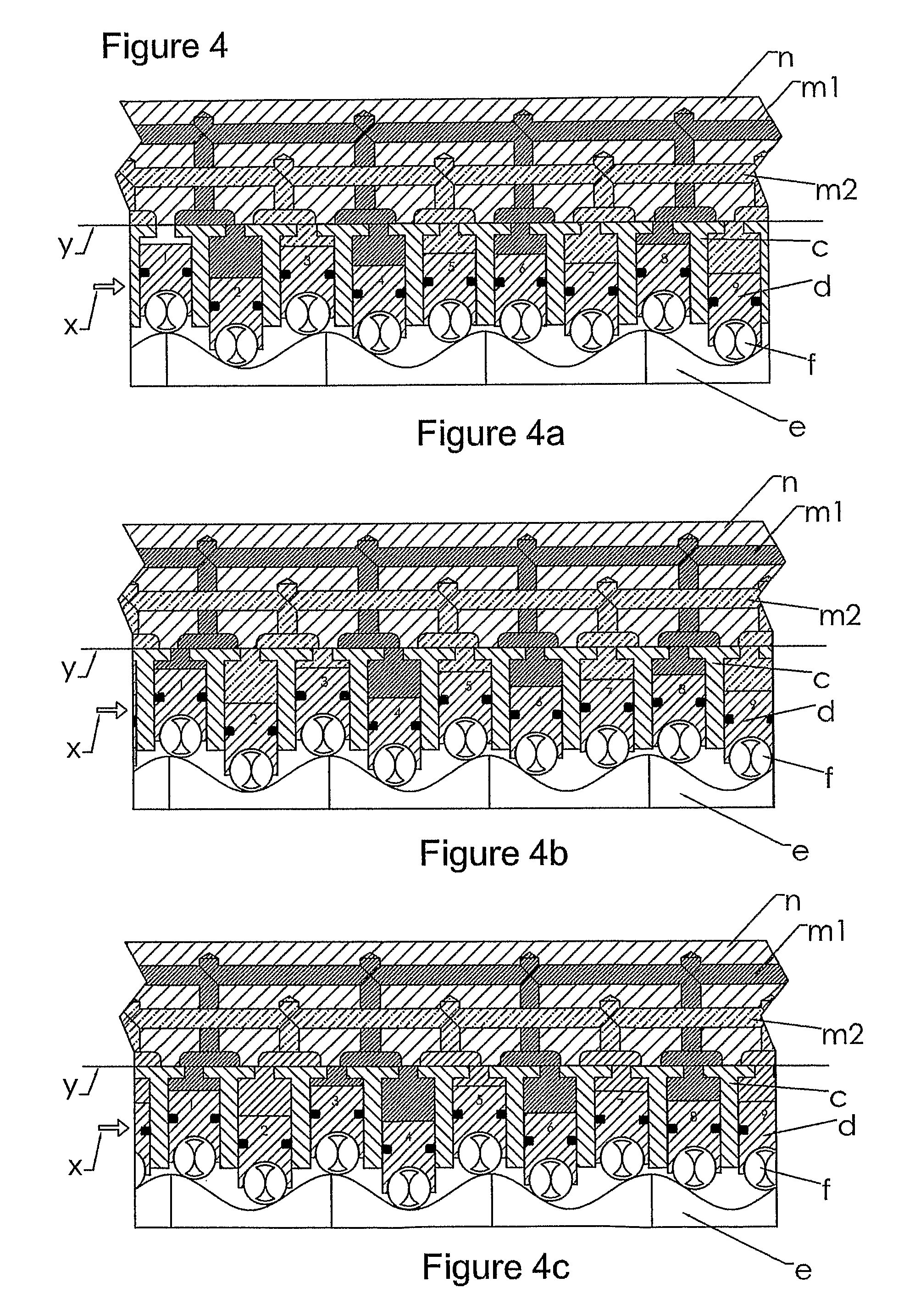
[0069]As can be seen in FIGS. 1 to 3 a shaft (a) is rigidly supported by a bearing (b) that is able to sustain radial and lateral loading. A cylinder block (c) is fixed to the shaft and is able to rotate about the shaft axis. The cylinder block (c) contains a plurality of bores equally spaced on a common pitch circle diameter (P.C.D.) concentric with the shaft axis. Each bore houses a reciprocating piston (d) and each piston (d) is provided at one end with a crown (d1) and at the other end with a spherical seating cup (d2), with a seal (d3) between each piston and the cylinder block. The pistons (d) are able to act on a cylindrical cam track (e) through balls (f) that are retained in the spherical seats of the pistons (d). The cam track (e) is engaged by the balls (f) and in which track the balls (f) are able to rotate. The P.C.D. of the cam track is concentric with the shaft axis and identical to the P.C.D of...


PUM


Abstract

A low pressure fluid powered motor or pump comprises a non-rotatable cover (k); an undulating lobe cam track (e) attached to the cover (k) and defining multiple crests and troughs; a rotatable cylinder block (c); at least three reciprocating pistons (d) each housed within a bore of the cylinder block (c) and each providing at one end a crown (d1), and at the other end a spherical seating cup (d2); a ball (f), adapted to engage with the cam track (e); a non-rotatable manifold block (n) incorporating a plurality of ports (s), each being radially disposed at equal intervals in an end face of the manifold block adjacent the pistons (d), with the ports (s) linked to galleries connected to a higher pressure delivery circuit, and a lower pressure return circuit, with the angular arrangement of the ports (s) being such that the higher pressure is supplied to the crown (d1) of each piston (d) only while the piston (d) is moving from a crest to a trough of the cam track (e), with a switch to the lower fluid pressure circuit as continued rotation of the cylinder block (c) moves a piston (d) from a trough to a crest; an output / input shaft (a) connected to the cylinder block (c); and a rotary shaft-mounted, spring biased commutation, multi-ported face plate (i) interposed between the cylinder block and the manifold block.

Description

RELATED / PRIORITY APPLICATION[0001]This application is a National Phase filing regarding International Application No. PCT / GB2006 / 001659, filed on May 9, 2006. International Application No. PCT / GB2006 / 001659 relies upon British Application No. GB 0509787.8, filed on May 12, 2005, for priority.FIELD OF THE INVENTION[0002]This invention relates to a fluid powered motor with a common design concept, intended for low pressure (<20 bar) delivery of water and water based fluid(s).BACKGROUND OF THE INVENTION[0003]The food industry extensively employs small electric motors with grease filled speed reduction gearboxes, to drive conveyors etc. As hygiene and non-contamination is of high importance scheduled wash down of equipment is a standard procedure. Apart from shutting down production, electric motors etc must be covered, and at start-up removed. Sometimes, operatives omit to remove covers resulting in overheating, and possibly contamination of the food product being processed / handled....

Claims


Application Information

Patent Timeline
Patent Type & Authority Patents(United States)
IPC IPC(8): F04B27/08F01B13/04F04B1/20
CPCF04B1/2021F04B1/2078Y10T74/18304
Inventor BRISLAND, MICHAEL JOHNBRISLAND, LEGAL REPRESENTATIVE, MARGARET LAVINA
Owner HYDRODRIVES TECH
Why Eureka
Try Eureka