Solenoid arrangement with segmented armature member for reducing radial force

a technology of radial force reduction and armature member, which is applied in the direction of magnets, operating means/releasing devices of valves, magnetic bodies, etc., can solve the problems of undesirable radial force acting, undesirable eccentricity of armatures, friction between components, etc., to minimize radial force, minimize radial force acting, and minimize friction between the armature member and any associated component surface.

Inactive Publication Date: 2013-04-16
BORGWARNER INC
View PDF7 Cites 2 Cited by
  • Summary
  • Abstract
  • Description
  • Claims
  • Application Information

AI Technical Summary

Benefits of technology

[0005]The present invention is directed to a solenoid arrangement or solenoid having an armature member that is segmented to help minimize the radial force due to eccentricity of the armature member. The solenoid arrangement has a magnetic coil that when energized will create magnetic flux in the magnetic circuit. An armature member is moveably disposed in association with air gaps of the magnetic circuit to impart force and do work. A pole piece is located in operable association with a central portion of the armature member such that the pole piece is partly circumscribed by the armature member. Inner and outer air gaps are located about the armature member such that eccentricity of the armature member results in a decrease in one of the air gaps and a corresponding increase in the other, e.g., eccentricity of the armature member toward the solenoid axis or pole piece reduces the associated inner air gap while increasing the corresponding outer air gap. A plurality of radial gaps segment the armature member and the segments are uniformly coupled about the circumference of a collar such that each segment is associated with a respective portion of the inner air gap and outer air gap. These radial gaps in the armature member interrupt the circumferential flux path about the armature member. Interrupting the circumferential flux path helps to inhibit the magnetic flux from “swirling” around the armature member to the side nearest to the pole piece, e.g., helps to inhibit the clustering or grouping and uneven distribution of magnetic flux. The radial force that results is significantly less than conventional solenoids. Thus, the friction between the armature member and any associated component surfaces, e.g., between a guide pin and bearing surfaces, is substantially obviated or reduced. It is understood that the use of a flux tube, which is required by conventional solenoids, can be omitted from the solenoid arrangement of the present invention. The improved solenoid arrangement of the present invention having an armature member that is segmented helps to minimize the radial force acting on the armature member due to eccentricity while substantially preserving the desirable level of axial force.

Problems solved by technology

Undesirable eccentricity of the armature is an inherent problem with solenoids.
Any eccentricity of the armature will cause uneven distribution of magnetic flux and will result in an undesirable radial force acting perpendicular to the solenoid axis.
Manufacturing imperfections in the solenoid components, clearance with the bearings associated with the armature, assembly of the solenoid components in less than perfect alignment, and the like can all contribute to eccentricity.
Thus, an increased radial force acting on the armature will be applied to any associated component surfaces, e.g., between an armature pin and bearing surfaces, resulting in friction between components.
Friction with the components degrades the performance of the solenoid and causes wear.

Method used


Image

  • Solenoid arrangement with segmented armature member for reducing radial force
  • Solenoid arrangement with segmented armature member for reducing radial force
  • Solenoid arrangement with segmented armature member for reducing radial force

Examples


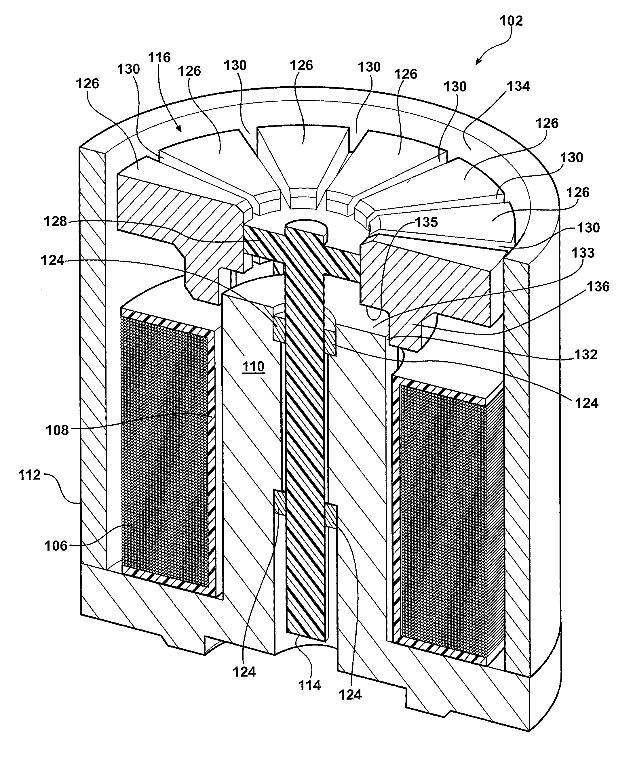
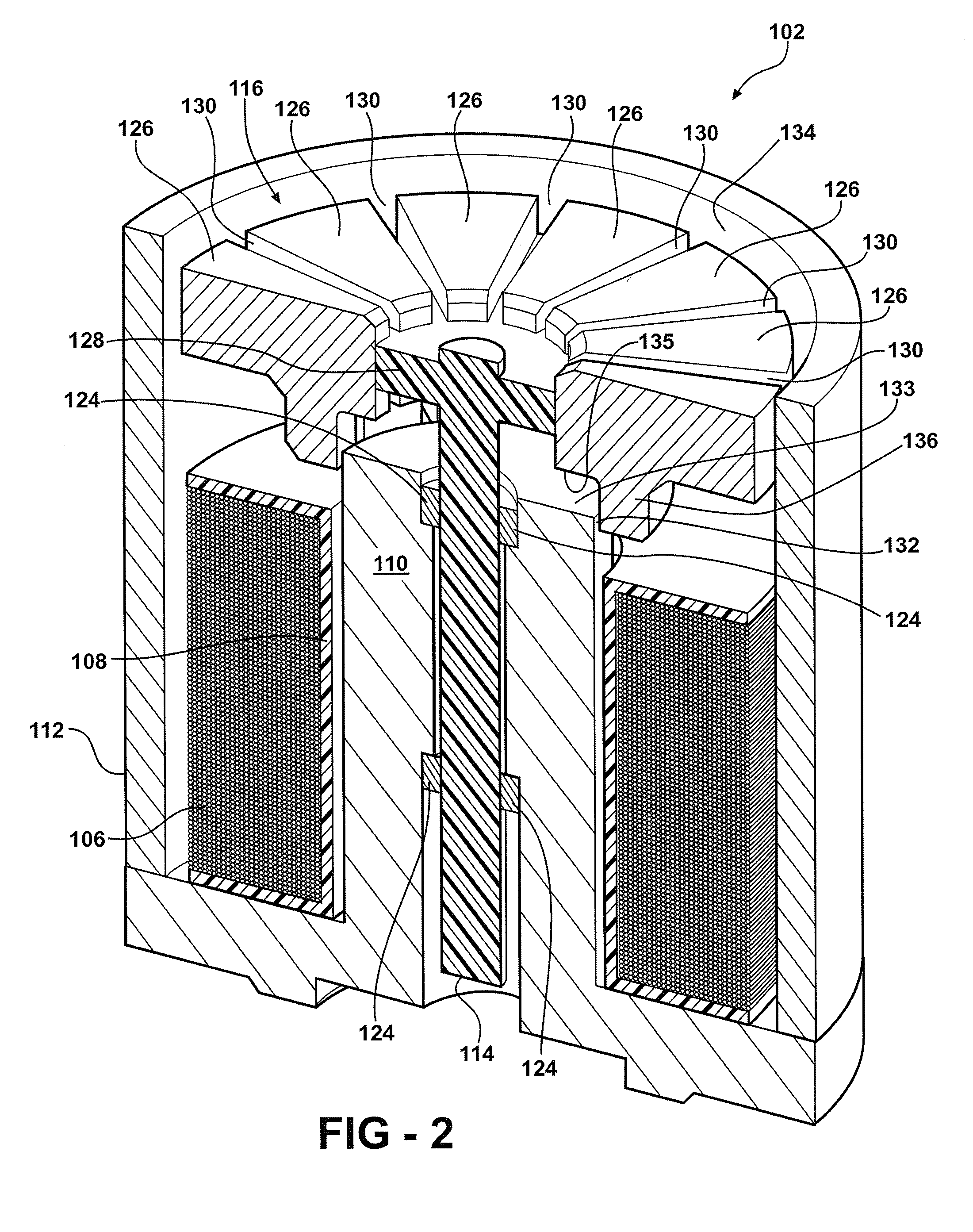
Embodiment Construction

[0020]The following description of the preferred embodiment(s) is merely exemplary in nature and is in no way intended to limit the invention, its application, or uses.

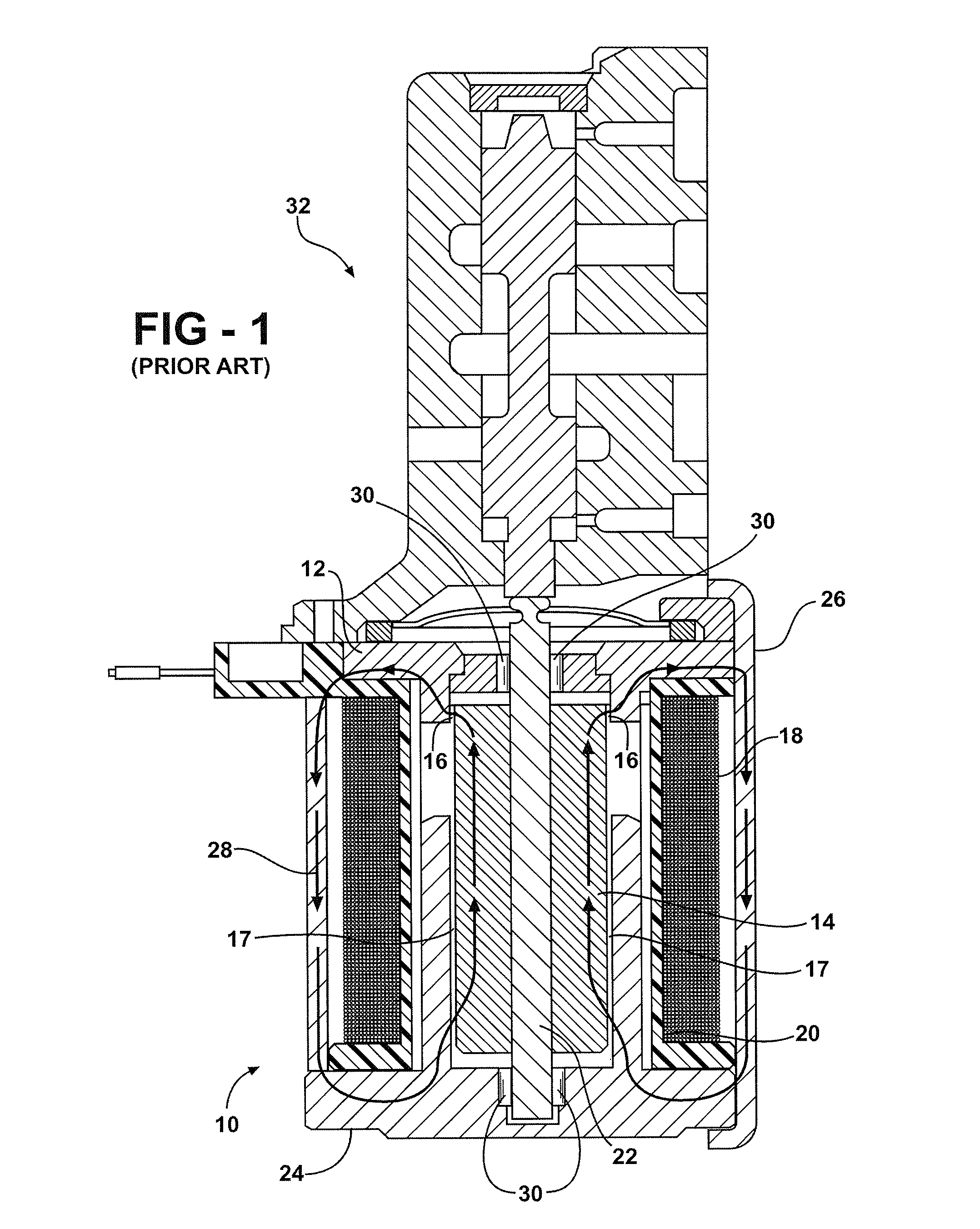
[0021]Referring now to FIG. 1, a cross sectional plan view showing a conventional prior art solenoid is shown generally at 10. The solenoid 10 has a pole piece 12 that partly overlaps and circumscribes an armature 14 forming a substantially narrow circumferential air gap, referred to as a working air gap 16, located between the pole piece 12 and the armature 14. The pole piece 12 is a stationary part toward which the armature 14 is magnetically attracted when a coil 18 is energized. The coil 18 at least partly circumscribes a bobbin 20. The armature 14 is formed as a single cylindrical piece having a central axial bore extending along its longitudinal length. The armature 14 and an armature pin 22 are assembled by press fit engagement wherein the armature pin 22 extends through the central axial bore of the armature 1...


PUM

PropertyMeasurementUnit
magnetic fluxaaaaaaaaaa
radial forceaaaaaaaaaa
non-magneticaaaaaaaaaa

Abstract

A solenoid arrangement having an armature member that is segmented to help minimize the radial force due to eccentricity of the armature member. The solenoid arrangement has a magnetic coil that when energized will create magnetic flux in the flux path. A pole piece is partly circumscribed by the armature member. Inner and outer air gaps are located about the armature member. Eccentricity of the armature member results in a decrease in one of the air gaps and a corresponding increase in the other. Radial gaps segment the armature member to interrupt the circumferential flux path about the armature member to inhibit magnetic flux from swirling to the side nearest the pole piece and to distribute magnetic flux substantially evenly. The radial force acting on the armature member is reduced resulting in reduced friction between solenoid components while substantially preserving the desirable level of axial force.

Description

FIELD OF THE INVENTION[0001]The present invention relates to a solenoid arrangement having an armature member that is segmented to reduce a radial force that occurs from armature eccentricity.BACKGROUND OF THE INVENTION[0002]Solenoids are generally known and used for a variety of purposes. In some applications it is useful to have a solenoid that provides a relatively constant force over a relatively long stroke. This type of solenoid, commonly called a linear solenoid, uses a variable overlap in the working air gap generally associated with an armature to generate an electromagnetic force in the direction of the solenoid axis extending along the longitudinal length of the armature. Undesirable eccentricity of the armature is an inherent problem with solenoids. Conventional solenoids have two air gaps disposed axially along the armature so that eccentricity of the armature causes both air gaps to be reduced. Any eccentricity of the armature will cause uneven distribution of magnetic...

Claims


Application Information

Patent Timeline
Patent Type & Authority Patents(United States)
IPC IPC(8): H01F3/00F16K31/02
CPCH01F7/16H01F2007/086H01F2007/083H01F7/08H01F7/14
Inventor DELAND, DANIEL L
Owner BORGWARNER INC
Why Eureka
Try Eureka