
Lamp assembly for ceiling fan

Active Publication Date: 2022-05-03
AIR COOL INDAL
View PDF3 Cites 1 Cited by
  • Summary
  • Abstract
  • Description
  • Claims
  • Application Information

AI Technical Summary

Benefits of technology

The present invention is a lamp assembly for a ceiling fan that allows for better heat dissipation and quicker installation. The lamp's thermal energy is transferred to the heat dissipation fins of the heat dissipation units, which are then dissipated through air flow generated by the ceiling fan. This results in a more efficient and effective heat-related solution, which can be easily and quickly installed.

Problems solved by technology

Due to the poor heat dissipation of the light-emitting diode (LED), the light-emitting diode (LED) is prone to overheating and burning out.

Method used


Image

  • Lamp assembly for ceiling fan
  • Lamp assembly for ceiling fan
  • Lamp assembly for ceiling fan

Examples


Embodiment Construction

[0014]Embodiments of the present invention will now be described, by way of example only, with reference to the accompanying drawings.

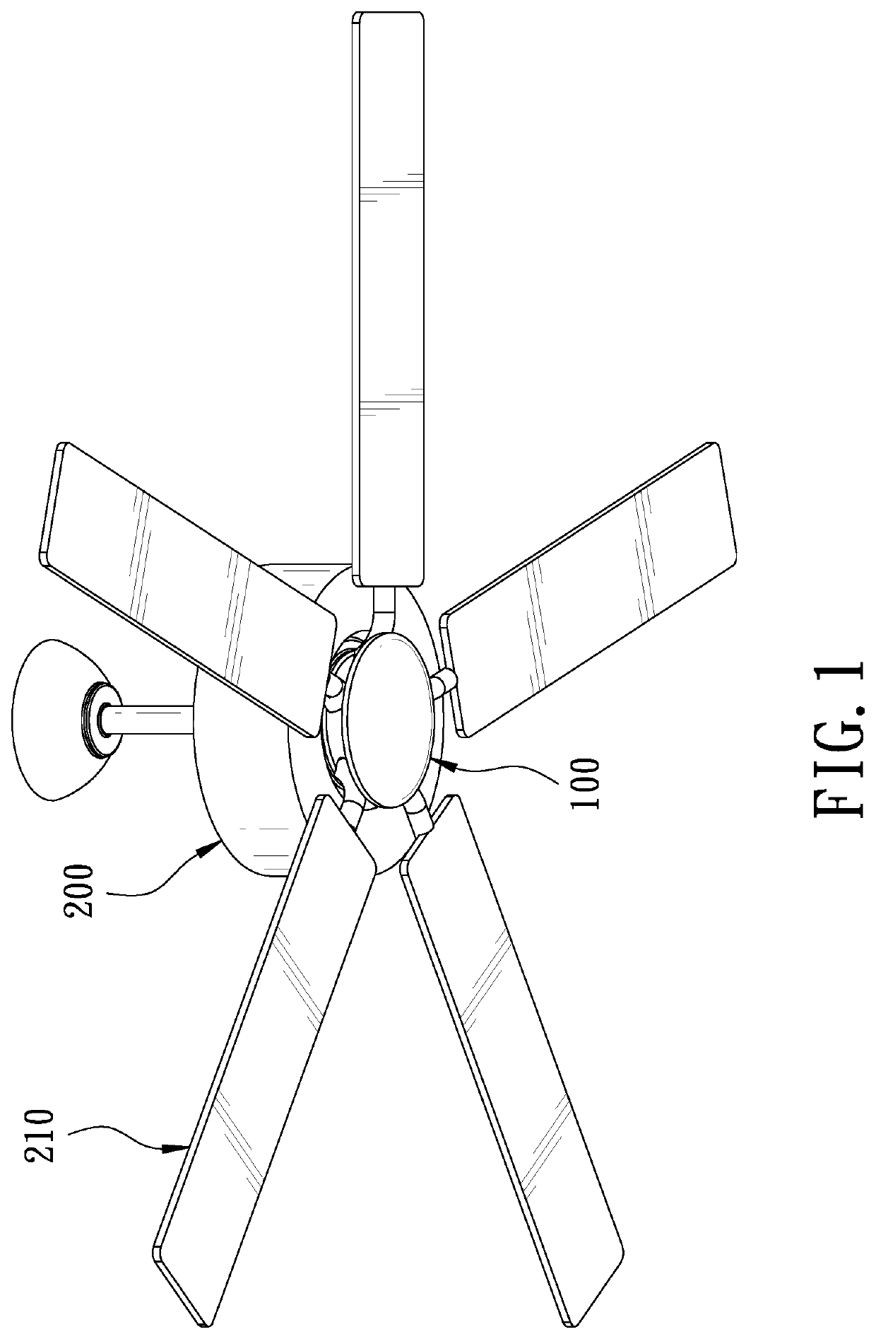
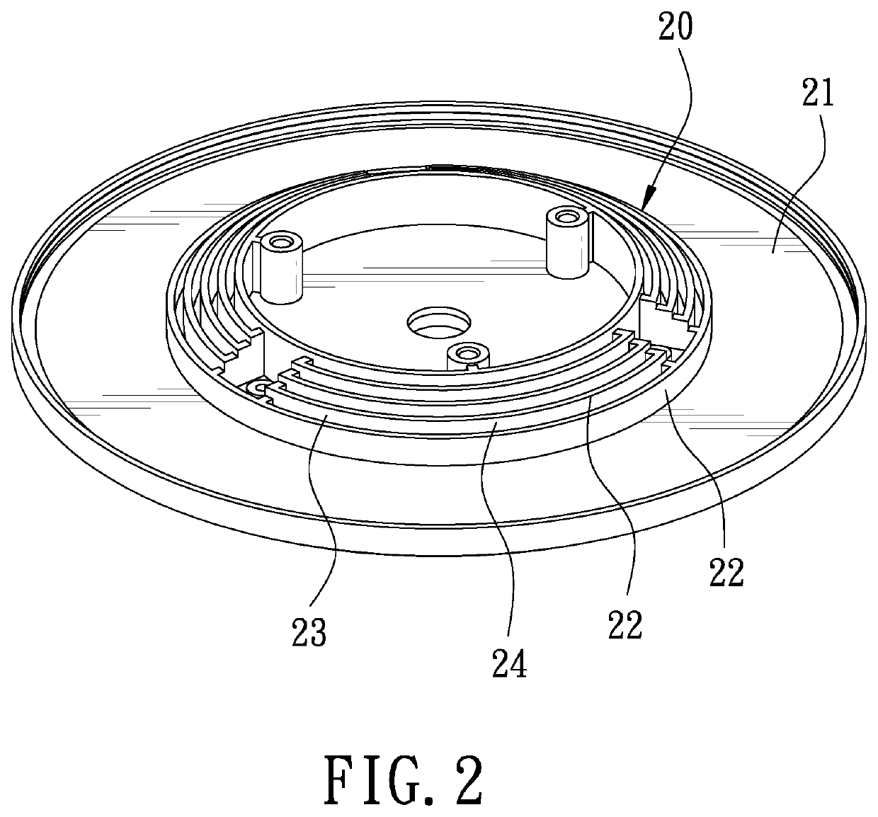
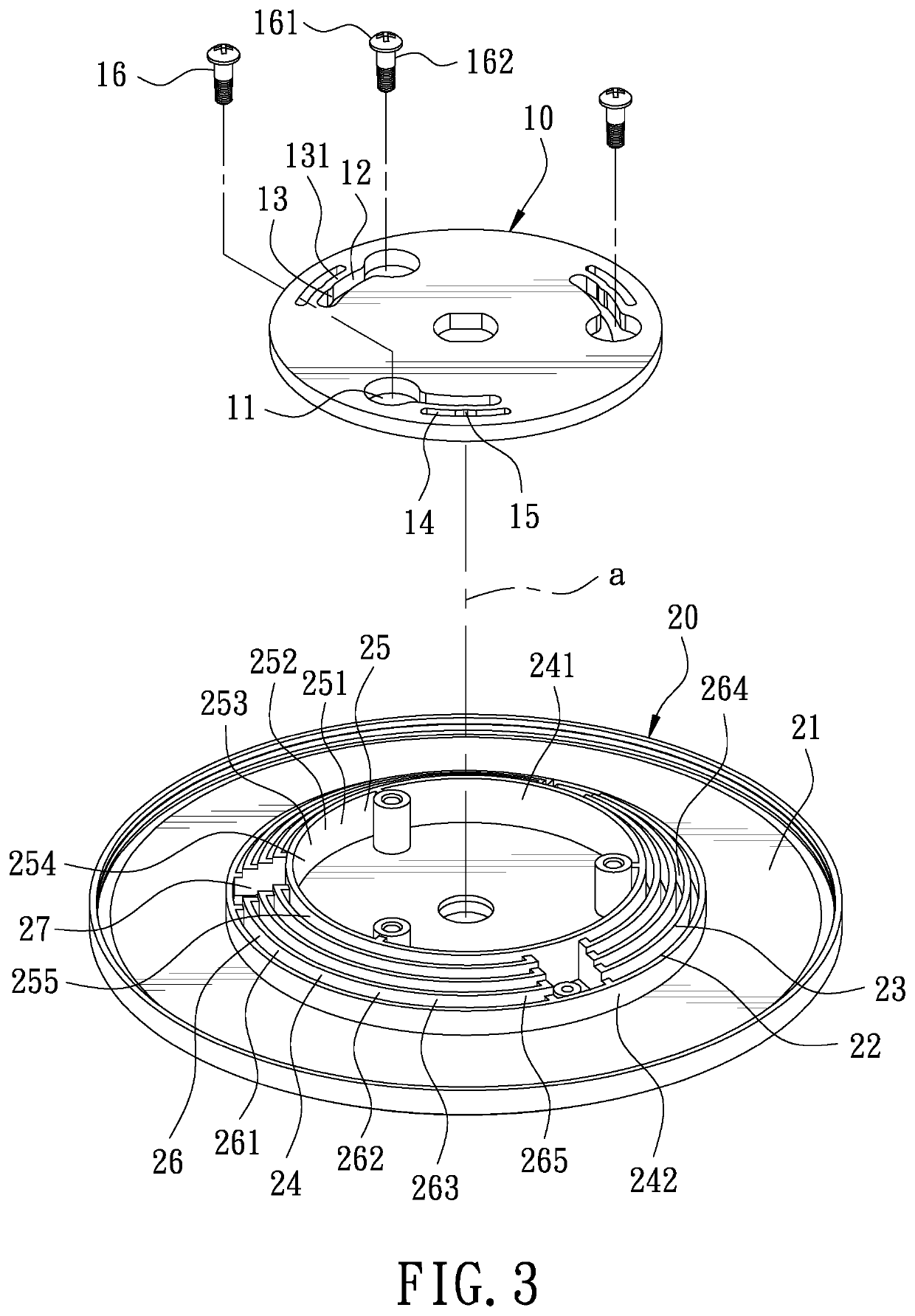
[0015]FIG. 1 is a perspective view in accordance with a preferred embodiment of the present invention. FIG. 2 is a partial perspective view in accordance with the preferred embodiment of the present invention. FIG. 3 is a partial exploded view in accordance with the preferred embodiment of the present invention. The present invention discloses a lamp assembly 100 for a ceiling fan. The lamp assembly 100 is installed to a ceiling fan 200. The ceiling fan 200 includes a plurality of blades 210. The ceiling fan 200 has a connecting seat 10. The lamp assembly 100 includes a heat dissipation module 20 and a lamp 30.

[0016]The connecting seat 10 is formed with a plurality of through positioning holes 11 each having a guide hole 12 extending from its one side along a rotation direction. The inner wall of a long side of the guide hole 12 is transversely provid...


PUM


Abstract

A lamp assembly installed to a ceiling fan includes a heat dissipation module and a lamp. The heat dissipation module has a heat dissipation body. The heat dissipation body is mounted to a connecting seat of the ceiling fan. The heat dissipation body includes a plurality of heat dissipation units on one side of the heat dissipation body adjacent to the connecting seat. The heat dissipation units have an axis. The heat dissipation units are sequentially arranged from inside to outside relative to the axis. The heat dissipation units each have at least one heat dissipation fin relative to the axis. The lamp is fixedly connected to another side of the heat dissipation body. The lamp assembly has a better heat dissipation effect and can be installed quickly.

Description

FIELD OF THE INVENTION[0001]The present invention relates to a lamp assembly, and more particularly to a lamp assembly for a ceiling fan.BACKGROUND OF THE INVENTION[0002]In the current technical field of ceiling fans, a lamp is generally installed beneath a ceiling fan. The lamp has a light-emitting member therein. In general, the light-emitting member of the lamp is a spiral energy-saving bulb. With the setting of the lamp, the ceiling fan has the functions of ventilation, cooling and illumination.[0003]However, with the rapid advancement of light-emitting diode (LED) technology, LED lamps are more energy-saving and lighter than traditional lamps, so LED lamps are widely used on the market. Due to the poor heat dissipation of the light-emitting diode (LED), the light-emitting diode (LED) is prone to overheating and burning out. Accordingly, the inventor of the present invention has devoted himself based on his many years of practical experiences to solve these problems.SUMMARY OF T...

Claims


Application Information

Patent Timeline
IPC IPC(8): F21V33/00F21V29/76F21V29/60F21Y115/10
CPCF21V29/763F21V29/60F21V33/0096F21Y2115/10
Inventor WANG, CLIFF
Owner AIR COOL INDAL
Learn More