
Mobile computing apparatus

Active Publication Date: 2012-08-02
INVENTEC CORP
View PDF11 Cites 8 Cited by
  • Summary
  • Abstract
  • Description
  • Claims
  • Application Information

AI Technical Summary

Benefits of technology

[0013]Accordingly, the present invention is a mobile computing apparatus, which solves the problem that, the heat-dissipation effect of the double-fan configuration type of the conventional mobile computing apparatus is undesirable, and thus the system of the mobile computing apparatus easily breaks down due to the excessively high temperature.
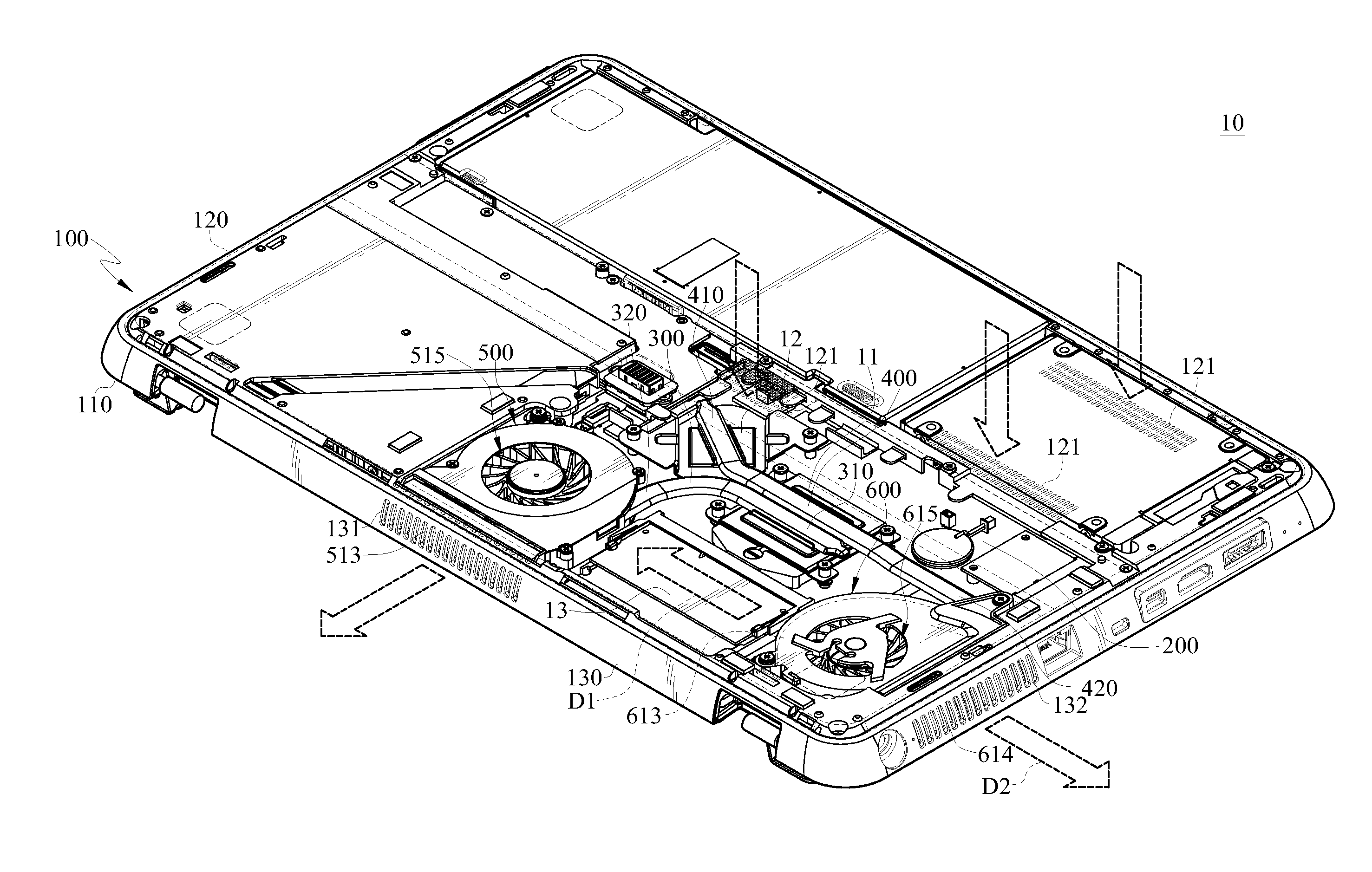
[0017]According to the mobile computing apparatus provided by the present invention, the centrifugal fan for convection exhausts to the inside of the shell, so that forced convection is generated in the mobile computing apparatus, and thus the hot air in the mobile computing apparatus does not stop at a specific area. In this way, since the hot air located in the specific area is constantly replaced by the cold air from other areas, the electronic components in the specific area can operate under a low working temperature in comparison with the prior art. Such mobile computing apparatus has better heat-dissipation effect than the conventional mobile computing apparatus, so that the stability of the entire system of the mobile computing apparatus further rises.

Problems solved by technology

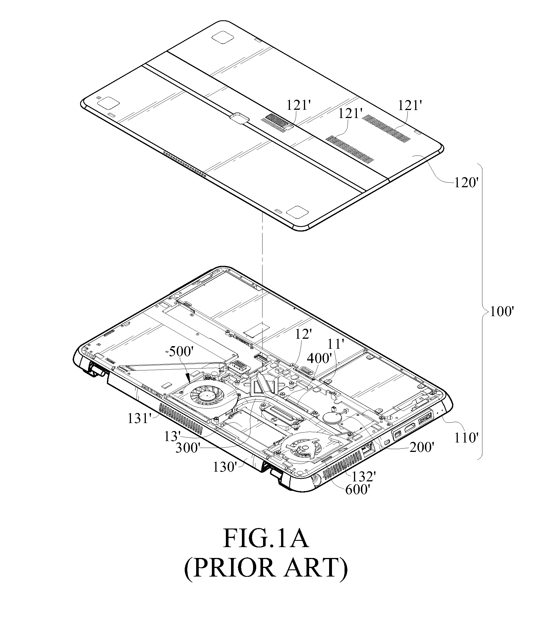
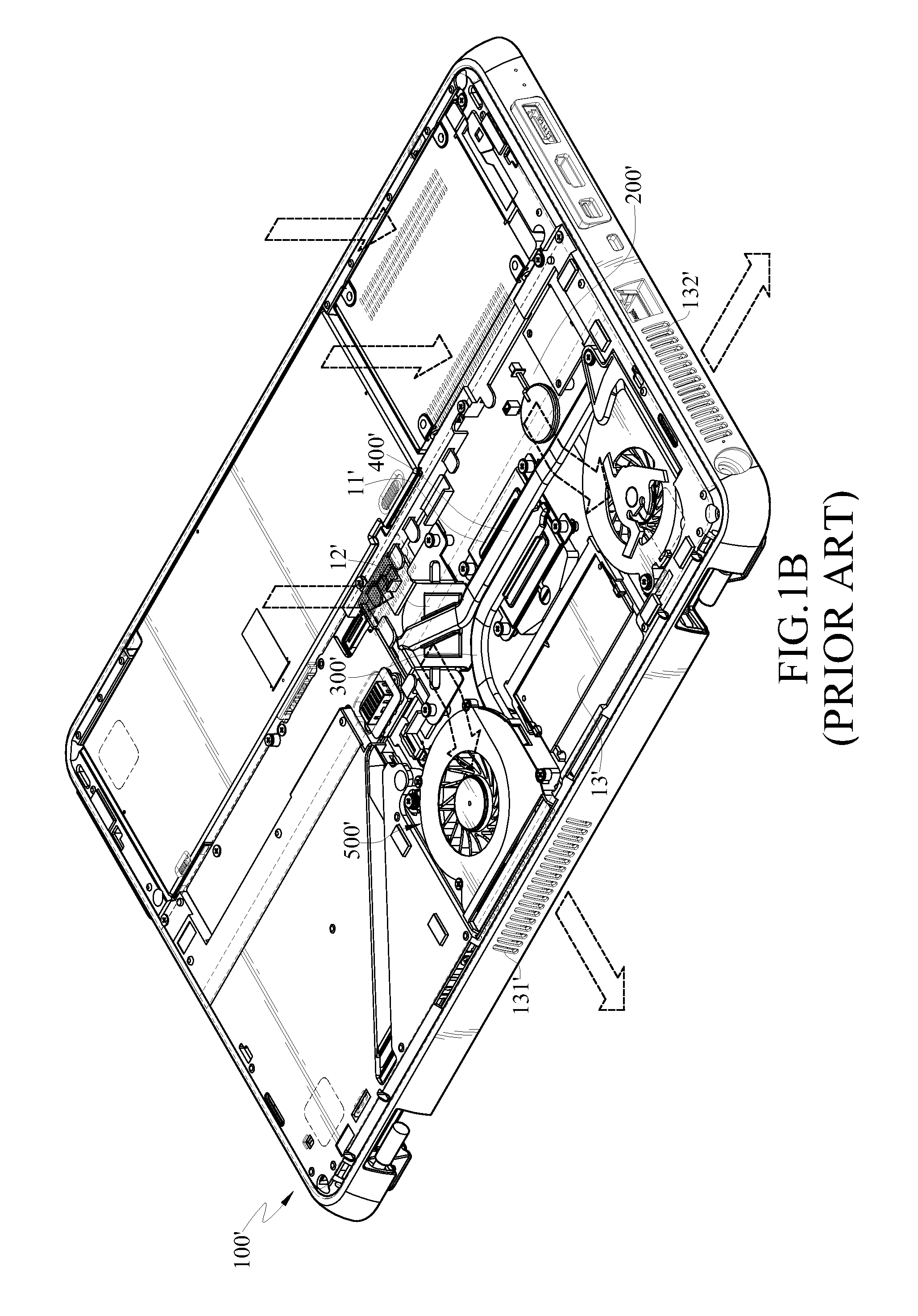
In this way, the temperature of the memory 13′ and the air around the memory 13′ continuously rises, so that a system of the mobile computing apparatus easily breaks down, and even the memory 13′ is damaged.
In addition, the first centrifugal fan 500′ and the second centrifugal fan 600′ respectively and independently form the paths of the gas flow with the gas vents 121′, and therefore the heat of heat-generation components being not located on the paths of the gas flow is easily accumulated on the adjacent bottom plate, so that the temperature of a part of the bottom plate is excessively high.

Method used


Image

  • Mobile computing apparatus
  • Mobile computing apparatus
  • Mobile computing apparatus

Examples


Embodiment Construction

[0028]Referring to FIGS. 2A to 2C, FIG. 2A is a schematic structural view of a mobile computing apparatus according to an embodiment of the present invention; FIG. 2B is a structural perspective view of a mobile computing apparatus according to an embodiment of the present invention; and FIG. 2C is a schematic structural view of a centrifugal fan for exhaust and a centrifugal fan for convection according to an embodiment of the present invention.

[0029]The mobile computing apparatus 10 in this embodiment may be a common notebook computer or a tablet computer. The mobile computing apparatus 10 comprises a shell 100, a circuit board 200, a first heat-dissipation module 300, a centrifugal fan for exhaust 500, and a centrifugal fan for convection 600.

[0030]The shell 100 in this embodiment comprises a top plate 110 and a bottom plate 120 being opposite to each other, and a side plate 130 connecting the bottom plate 120 and the top plate 110, in which the side plate 130 has a first through...


PUM


Abstract

A mobile computing apparatus includes a shell, a circuit board, a first heat-dissipation module, a centrifugal fan for exhaust, and a centrifugal fan for convection. The shell has a first through hole. The circuit board is disposed on the shell, and has a first heat-generation device. The first heat-dissipation module has a first heat-absorption end and a first heat-dissipation end, and the first heat-absorption end thermally contacts with the first heat-generation device. The centrifugal fan for exhaust has a first gas outlet, and the first heat-dissipation end is located between the first gas outlet and the first through hole, so that the centrifugal fan for exhaust exhausts to an outside of the shell. The centrifugal fan for convection is configured in the shell, and exhausts to an inside of the shell. Therefore, gas flow circulation occurs in the shell, so that the mobile computing apparatus has a desirable heat-dissipation effect.

Description

CROSS-REFERENCE TO RELATED APPLICATIONS[0001]This non-provisional application claims priority under 35 U.S.C. §119(a) on Patent Application No(s). 100103734 filed in Taiwan, R.O.C. on Jan. 31, 2011, the entire contents of which are hereby incorporated by reference.BACKGROUND OF THE INVENTION[0002]1. Field of the Invention[0003]The present invention relates to a mobile computing apparatus, and in particular, to a mobile computing apparatus having a plurality of heat-dissipation fans.[0004]2. Related Art[0005]With the constant development of technology, current daily necessities develop toward digitization and informatization. For example, a mobile computing apparatus, such as a notebook computer and a tablet computer, is easily carried by a user, so as to be freely used by the user in any occasions.[0006]However, under the trend of technology development, the researchers devote their efforts to continuously developing the mobile computing apparatus toward the objectives of having hig...

Claims


Application Information

Patent Timeline
IPC IPC(8): G06F1/20
CPCG06F1/203
Inventor WANG, FENG-KUCHENG, YI-LUN
Owner INVENTEC CORP
Learn More