
Electrical connector

Pending Publication Date: 2022-02-03
AMPHENOL COMML PROD CHENGDU
View PDF10 Cites 0 Cited by
  • Summary
  • Abstract
  • Description
  • Claims
  • Application Information

AI Technical Summary

Benefits of technology

The invention relates to a design for an electronic card which includes a reinforcing member to prevent deformation or cracking of the card when it is impacted by external force. The reinforcing member maintains the shape of the card and absorbs the impact force, improving its impact resistance. The design also allows for good heat dissipation, ensuring stable performance of the electronic system even in poor ventilation environments. Overall, the design improves the reliability and stability of the electronic card.

Problems solved by technology

However, the PCBs will generate heat during operation.

Method used


Image

  • Electrical connector
  • Electrical connector
  • Electrical connector

Examples


Embodiment Construction

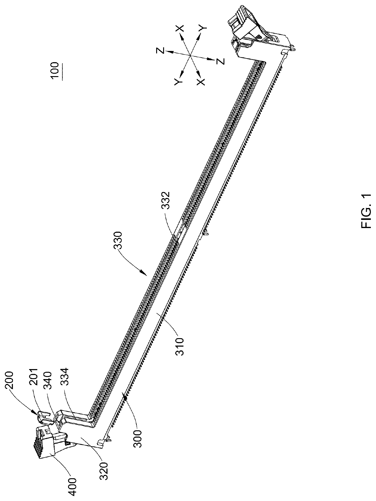
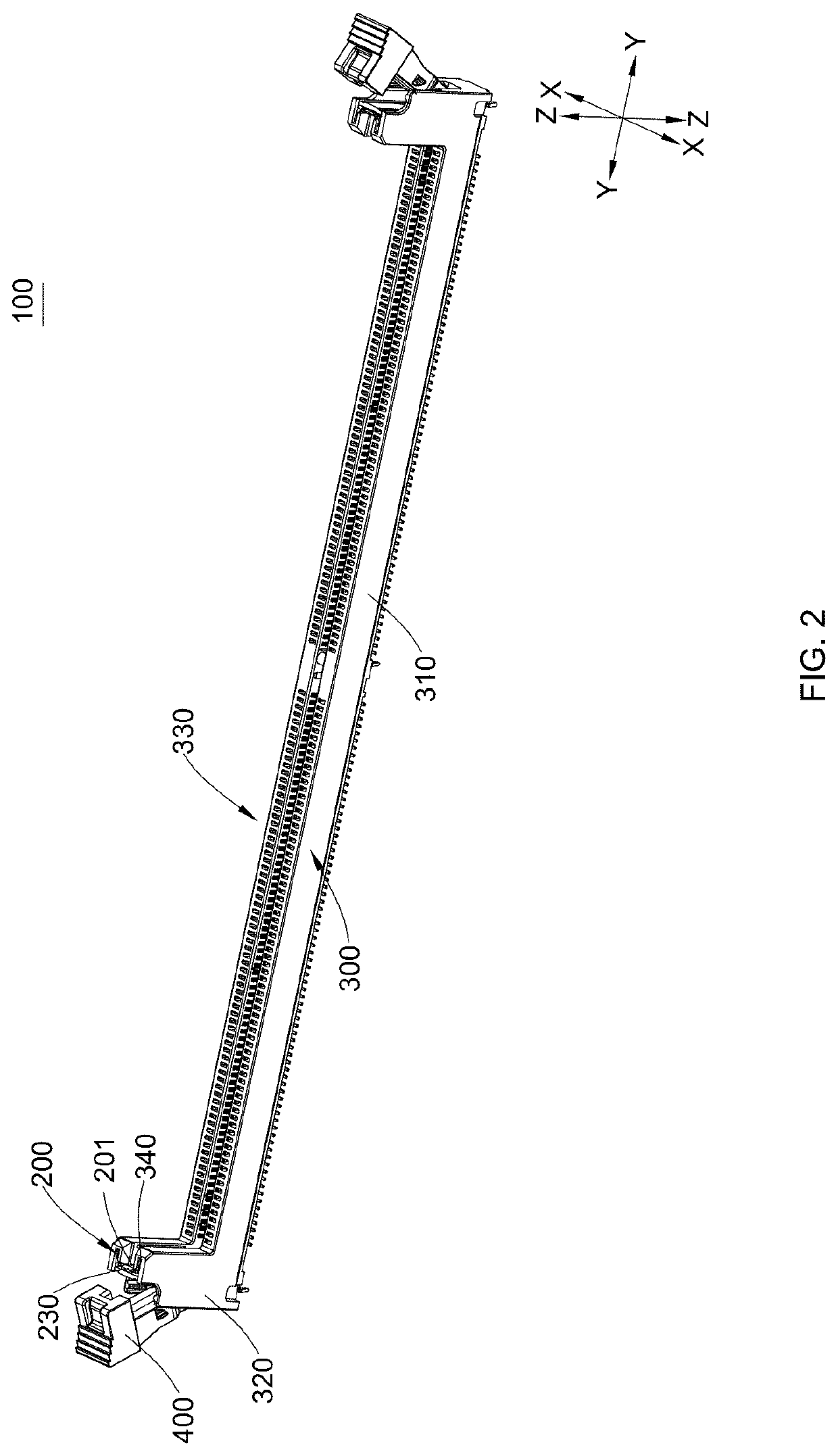
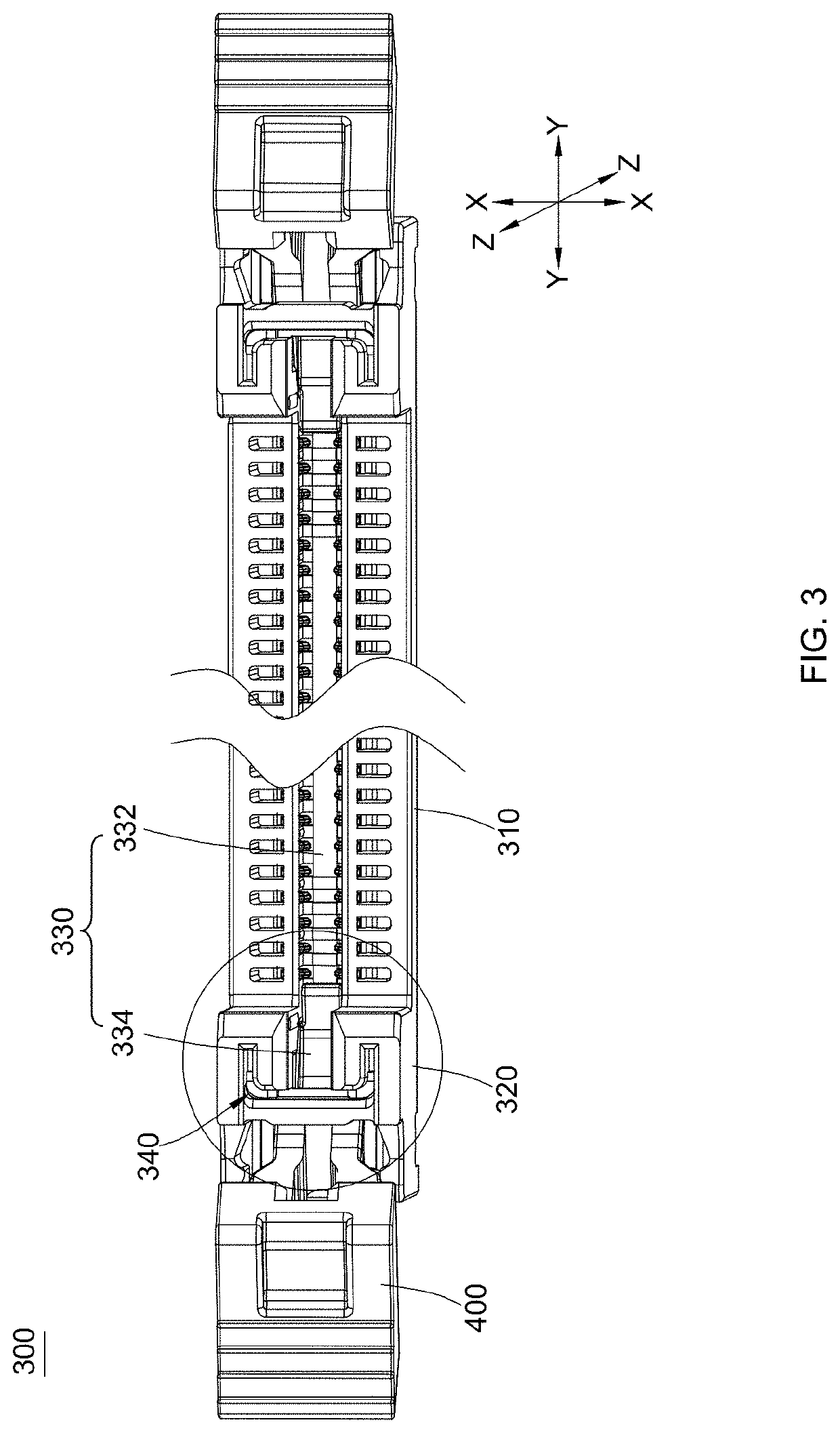
[0064]The inventors have recognized and appreciated designs for electrical connectors that contribute to reliable performance of systems using those electrical connectors. In some systems, a performance advantage may be achieved by making connectors narrower than conventional connectors. However, in a card edge connector, making the connector narrower can increase the likelihood that the connector will be damaged by a force applied to the connector as a result of vibration or other operating conditions of the system.

[0065]For example, in a system in which multiple PCBs are mounted to a mainboard in parallel with channels for cooling air to flow between the PCBs, the connectors may constrict those channels and interface with the airflow. As a result, the heat generated by the PCBs is not efficiently diffused through the channel, which may cause adverse effects in the operation of the connectors due to overheating of the PCBs. However, making the connectors narrower, so that the chann...


PUM


Abstract

The present disclosure provides an electrical connector. The electrical connector includes an insulating body and one or more reinforcing members. The insulating body comprises a pair of side portions which extend in a longitudinal direction, and a pair of tower portions which are connected to respective ends of the pair of side portions. The pair of side portions and the pair of tower portions form a longitudinal card slot. The ends of the card slot extend into the pair of tower portions respectively. A reinforcing member may be arranged in a tower portion. When an electronic card is inserted into the card slot, the one or more reinforcing members can maintain the shape of the tower portions and prevent deformation or cracking of the tower portions when the electronic card is impacted by an external force.

Description

CROSS-REFERENCE TO RELATED APPLICATIONS[0001]This application claims priority to and the benefit of Chinese Patent Application Serial Nos. 202022974284.8 and 202011458813.7, filed on Dec. 11, 2020. This application also claims priority to and the benefit of Chinese Patent Application Serial Nos. 202021557848.1 and 202010756166.1, filed on Jul. 31, 2020. The entire contents of these applications are incorporated herein by reference in their entirety.TECHNICAL FIELD[0002]The present disclosure relates to an electrical connector.BACKGROUND[0003]An electrical connector in an electronic system is configured to connect circuits on one printed circuit board (PCB) to the circuits on another PCB. For some systems, it is easier and more cost-effective to manufacture most of the circuits of the system on separate electronic assemblies, for example, PCBs. The electronic assemblies may be connected together by an electrical connector. A common example is a memory card inserted into the electrica...

Claims


Application Information

Patent Timeline
IPC IPC(8): H01R13/502H01R12/73H01R13/627
CPCH01R13/502H01R13/6273H01R12/737H01R12/721
Inventor HU, XIAODONGGUO, BRYANYANG, KUI
Owner AMPHENOL COMML PROD CHENGDU
Learn More