

Aircraft tire
a technology for aircraft and tires, applied in the field of aircraft tires, can solve the problems of aircraft manufacturers demanding stringent tire weight reduction requirements, and the improvement of the separation durability at the end of reinforcing members, and achieve the effect of satisfying the separation durability of carcass ply ends and light weigh
Active Publication Date: 2022-05-10
BRIDGESTONE CORP
View PDF20 Cites 0 Cited by
- Summary
- Abstract
- Description
- Claims
- Application Information
AI Technical Summary
Benefits of technology
The solution provides an aircraft tire with satisfactory light weight and separation durability of carcass ply ends, inhibiting shear deformation and ensuring uniform tension, thus improving durability and reducing weight effectively.
Problems solved by technology
Thus, for example, an improvement in the separation durability at the ends of the reinforcing members presents a major challenge.
In addition, aircraft manufacturers are making stringent demands on tire weight reduction.
Method used
View moreImage
Smart ImageViewing Examples

Examples
examples
[0035]The tire of the present invention will now be described in detail by way of Examples.
Login to View More PUM
| Property | Measurement | Unit |
|---|---|---|
| elongation at break | aaaaa | aaaaa |
| elongation at break | aaaaa | aaaaa |
| angle | aaaaa | aaaaa |
Abstract
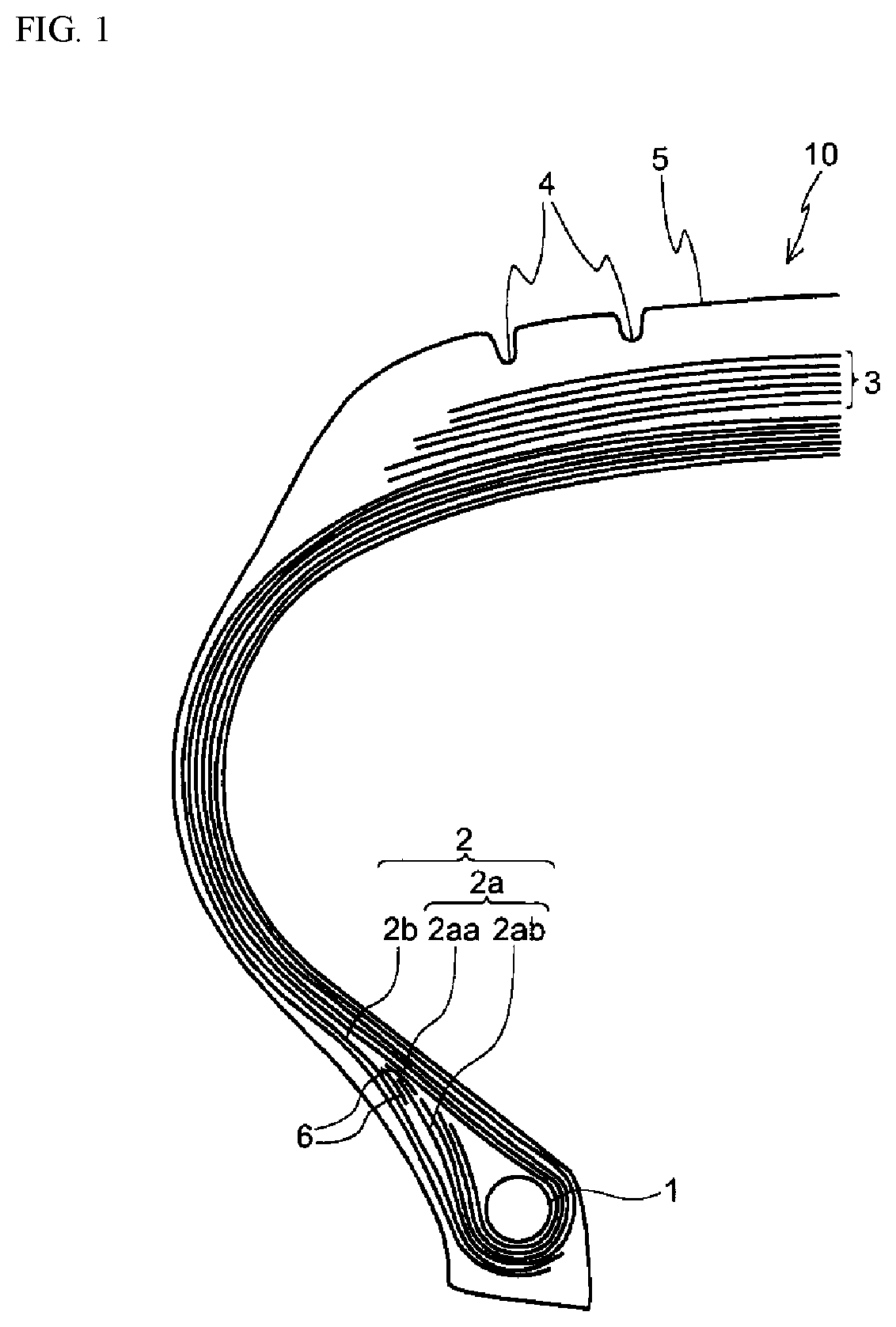
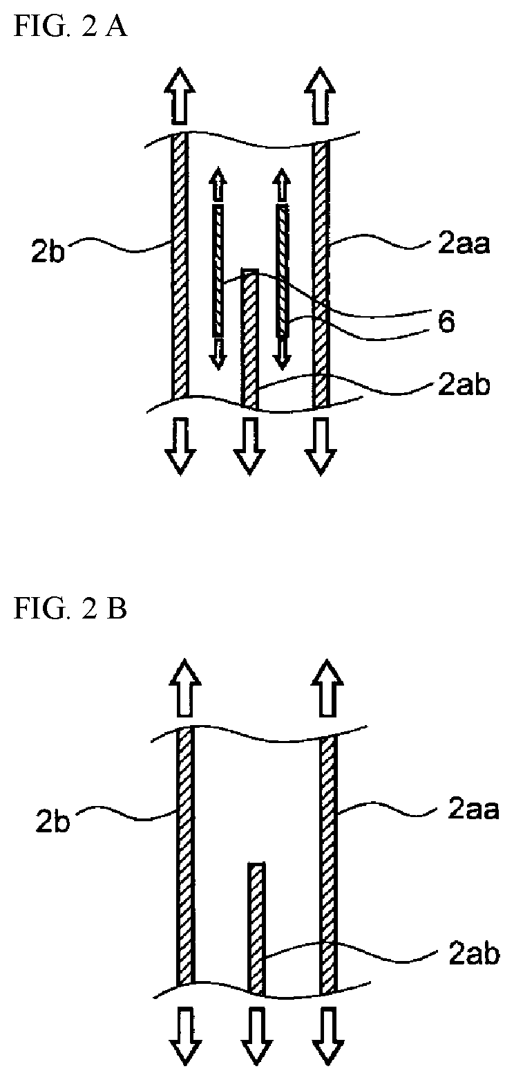
Provided is an aircraft tire which has both satisfactory light weight and satisfactory separation durability of carcass ply ends. An aircraft tire (10) includes a pair of bead cores (1), and a carcass (2) extending between the pair of the bead cores (1). In this aircraft tire (10), the carcass (2) includes at least one layer of a turn-up ply (2a) which is composed of a main body (2aa) and folded portions (2ab), and at least one layer of a down ply (2b) which covers a tire width-direction outer side of the respective folded portions (2ab) of the turn-up ply (2a) and extends to at least a tire radial-direction inner side of the respective bead cores (1); rubber-cord reinforcing members (6) are each arranged between the main body (2aa) of an outermost turn-up ply (2a) and the folded portion (2ab) of the turn-up ply (2a) extending to a tire radial-direction outermost side, and between the folded portion (2ab) of the turn-up ply (2a) extending to the tire radial-direction outermost side and an innermost down ply (2b); and cords of the rubber-cord reinforcing members (6) have an elongation at break of not less than 30%.
Description
CROSS REFERENCE TO RELATED APPLICATIONS[0001]This application is a National Stage of International Application No. PCT / JP2018 / 043049 filed Nov. 21, 2018, claiming priority based on Japanese Patent Application No. 2017-239014 filed Dec. 13, 2017.TECHNICAL FIELD[0002]The present invention relates to an aircraft tire (hereinafter, also simply referred to as “tire”), more particularly an aircraft tire which has both satisfactory light weight and satisfactory separation durability of carcass ply ends.BACKGROUND ART[0003]Since aircraft tires are, because of their application, used under the conditions of a higher internal pressure and a higher load as compared to those tires used on passenger vehicles, a larger tension is applied to the ends of their reinforcing members. Thus, for example, an improvement in the separation durability at the ends of the reinforcing members presents a major challenge. In addition, aircraft manufacturers are making stringent demands on tire weight reduction. ...
Claims
Login to View More Application Information
Patent Timeline
 Patent Type & AuthorityPatents(United States)
IPC IPC(8): B60C15/06B60C9/08
CPCB60C9/08B60C15/0628B60C2015/0692B60C2200/02B60C2015/0639B60C2015/0642B60C2015/065B60C2015/0685B60C15/0018B60C15/0027D02G3/48
InventorSUZUMORI, KIICHIRO
OwnerBRIDGESTONE CORP