

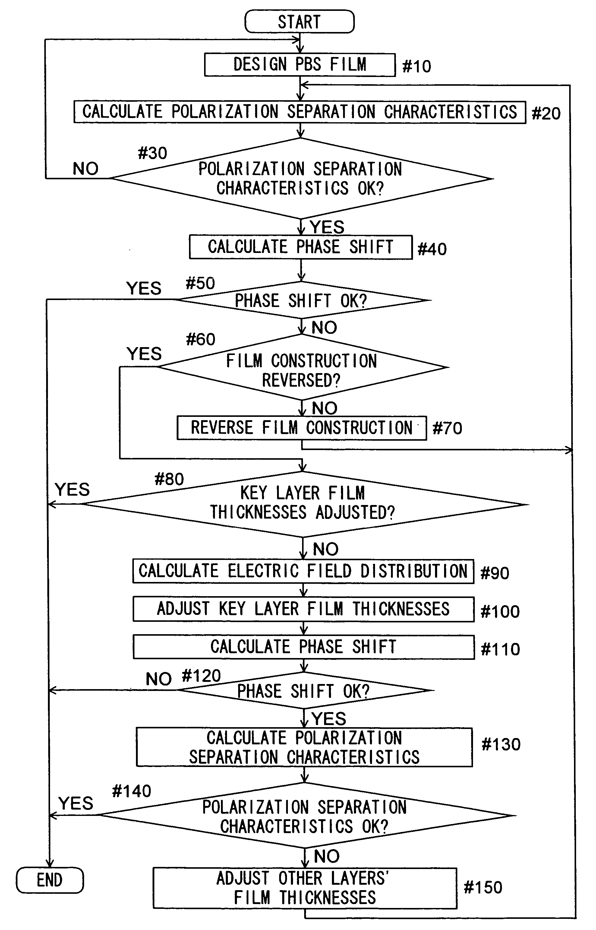
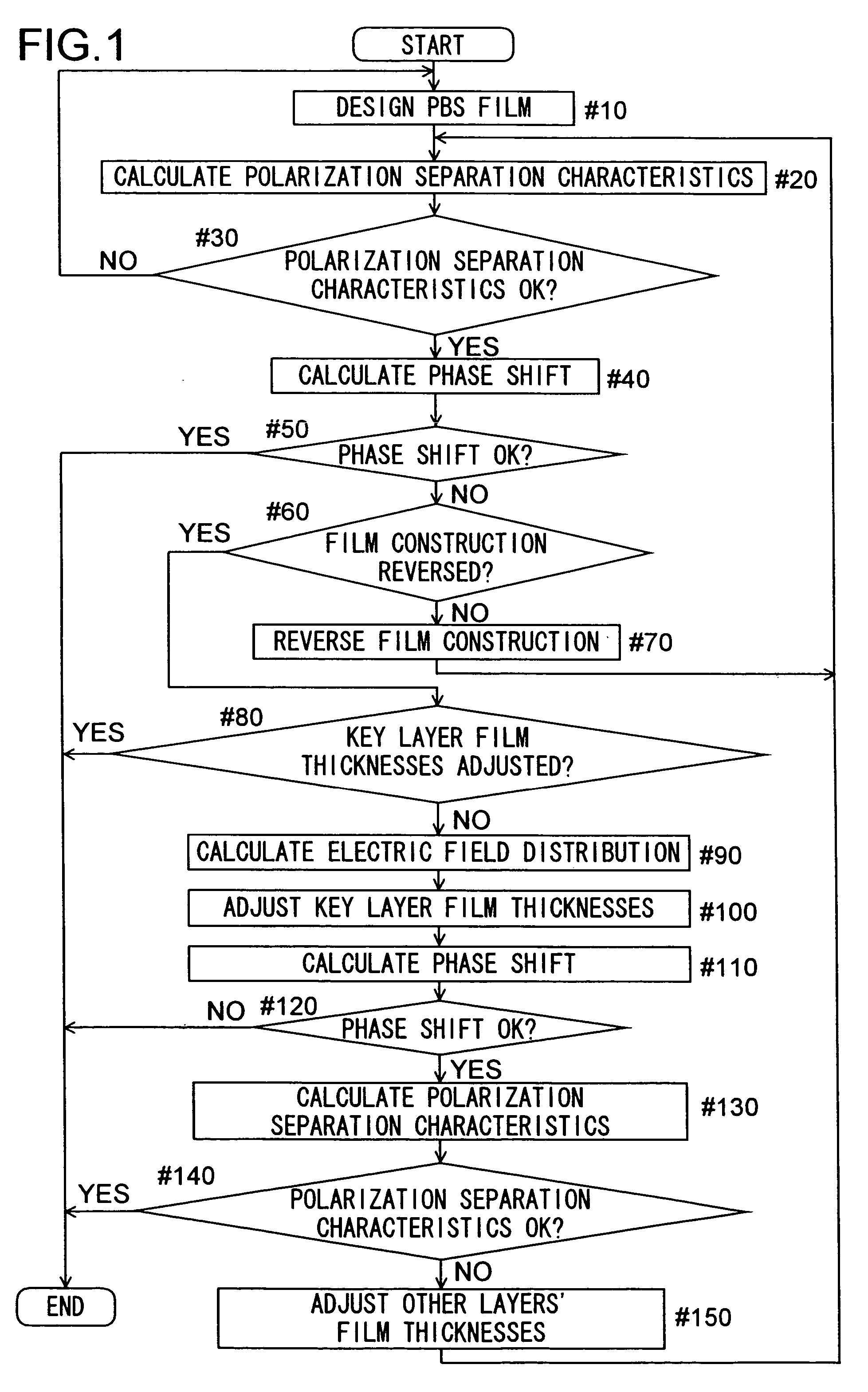
Method of phase shift adjustment of a polarization beam splitter film
a splitter film and phase shift adjustment technology, applied in the field of phase shift adjustment of polarization beam splitter films, can solve the problems of unsatisfactory polarization separation, difficult to achieve, and inability to obtain satisfactory polarization separation characteristics, so as to facilitate reflection-induced phase shift, satisfactory polarization separation, and high wavefront accuracy
- Summary
- Abstract
- Description
- Claims
- Application Information
AI Technical Summary
Benefits of technology
Problems solved by technology
Method used
Image

Examples
Embodiment Construction
[0054] Hereinafter, polarization beam splitter films according to the present invention, a method for adjusting the phase shift hereof, and other features of the present invention will be described with reference to the drawings. In the following description, the polarization separation splitters (PBSs) presented are all so constructed that first a polarization beam splitter film is formed on one glass substrate and then the loose end of the polarization beam splitter film is bonded to another glass substrate with an adhesive layer interposed in between so that the polarization beam splitter film is sandwiched between the two glass substrates. It should be understood, however, that this is not intended to restrict the construction of those PBSs in any way. For example, instead of forming a polarization beam splitter film between substrates, it is also possible to form a polarization beam splitter film on a transparent substrate and then coat the polarization beam splitter film with ...
PUM
 Abstract
Description
Claims
Application Information