Amplifying apparatus

Active Publication Date: 2020-11-12
MURATA MFG CO LTD
View PDF0 Cites 2 Cited by
  • Summary
  • Abstract
  • Description
  • Claims
  • Application Information

AI Technical Summary

Benefits of technology

The present invention aims to provide an amplifier that can achieve both high gain and linearity easily.

Problems solved by technology

On the other hand, strong electric coupling also occurs, and thus parasitic capacitance is developed between the gate and source of the amplifier, and the gain of the amplifier circuit greatly decreases.
Thus, it is difficult to achieve both gain and linearity required for communication in a relatively high frequency band used in recent years.

Method used


Image

  • Amplifying apparatus
  • Amplifying apparatus
  • Amplifying apparatus

Examples


embodiment 1

[0024]An amplifying apparatus according to Embodiment 1 will be described with reference to an example of an amplifying apparatus having negative feedback formed by the magnetic coupling between the inductors.

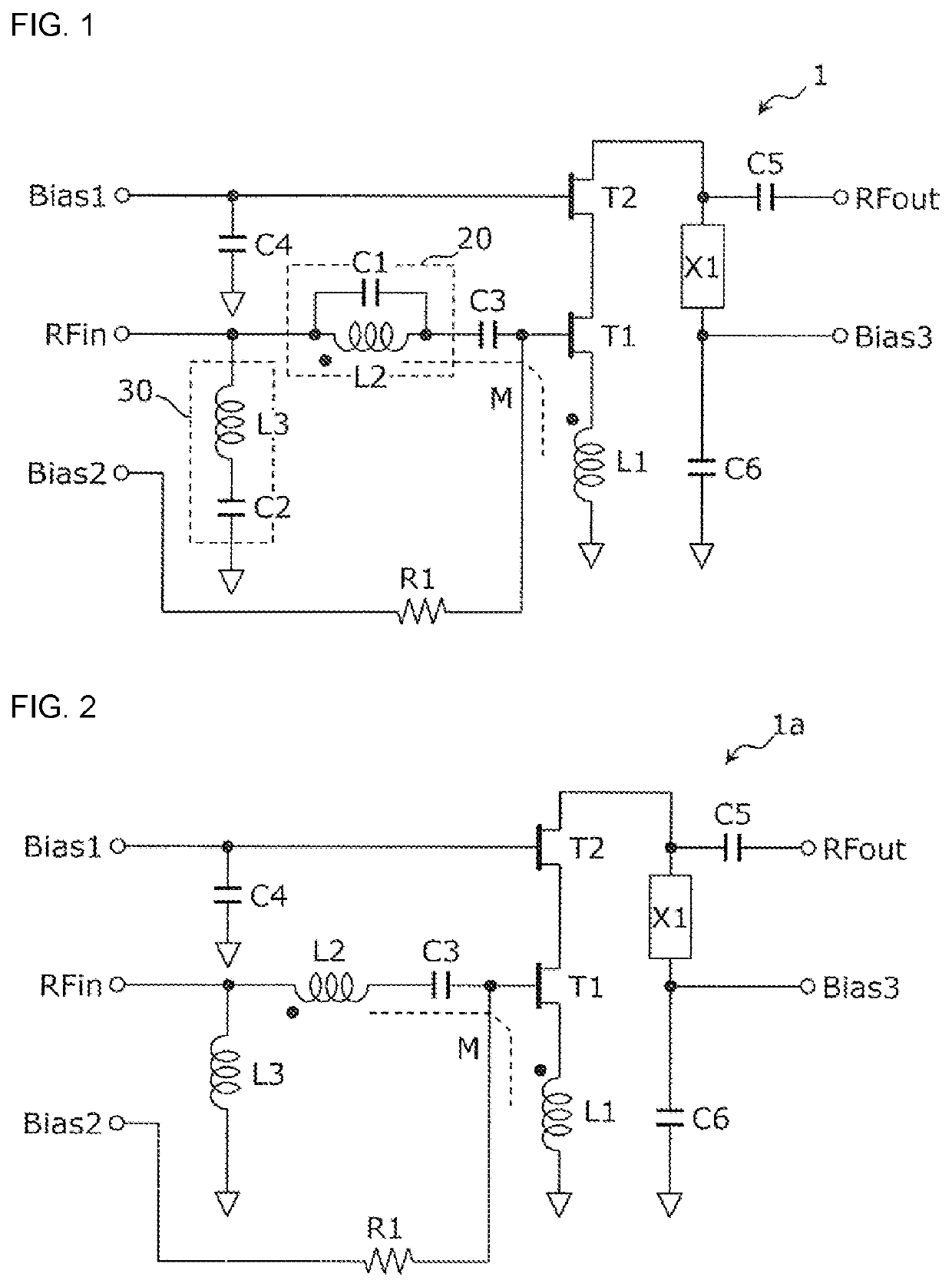
[0025]FIG. 1 is a circuit diagram illustrating an example of a circuit configuration of the amplifying apparatus according to Embodiment 1. As illustrated in FIG. 1, an amplifying apparatus 1 includes transistors T1, T2, inductors L1, L2, L3, capacitors C1, C2, C3, C4, C5, C6, a reactance element X1, and a resistor R1.

[0026]The transistors T1 and T2 constitute, as an example, a cascode amplifier. The transistor T1 is a transistor in a first stage of the cascode amplifier. Note that, the amplifier is not limited to the cascode amplifier. For example, the transistor T1 alone may constitute a source grounded type amplifier.

[0027]The inductor L1 is connected between a source of the transistor T1 and a ground (indicated by a small triangle in FIG. 1). By providing the inductor L1, i...

example 2

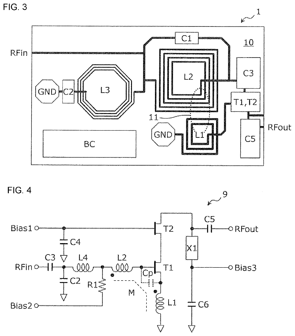
[0057]an amplifying apparatus having the circuit configuration (FIG. 2) of the amplifying apparatus 1a, in which the inductors L1 and L2 are arranged so as not to overlap each other (FIG. 3).

example 1

COMPLARATIVE EXAMPLE 1

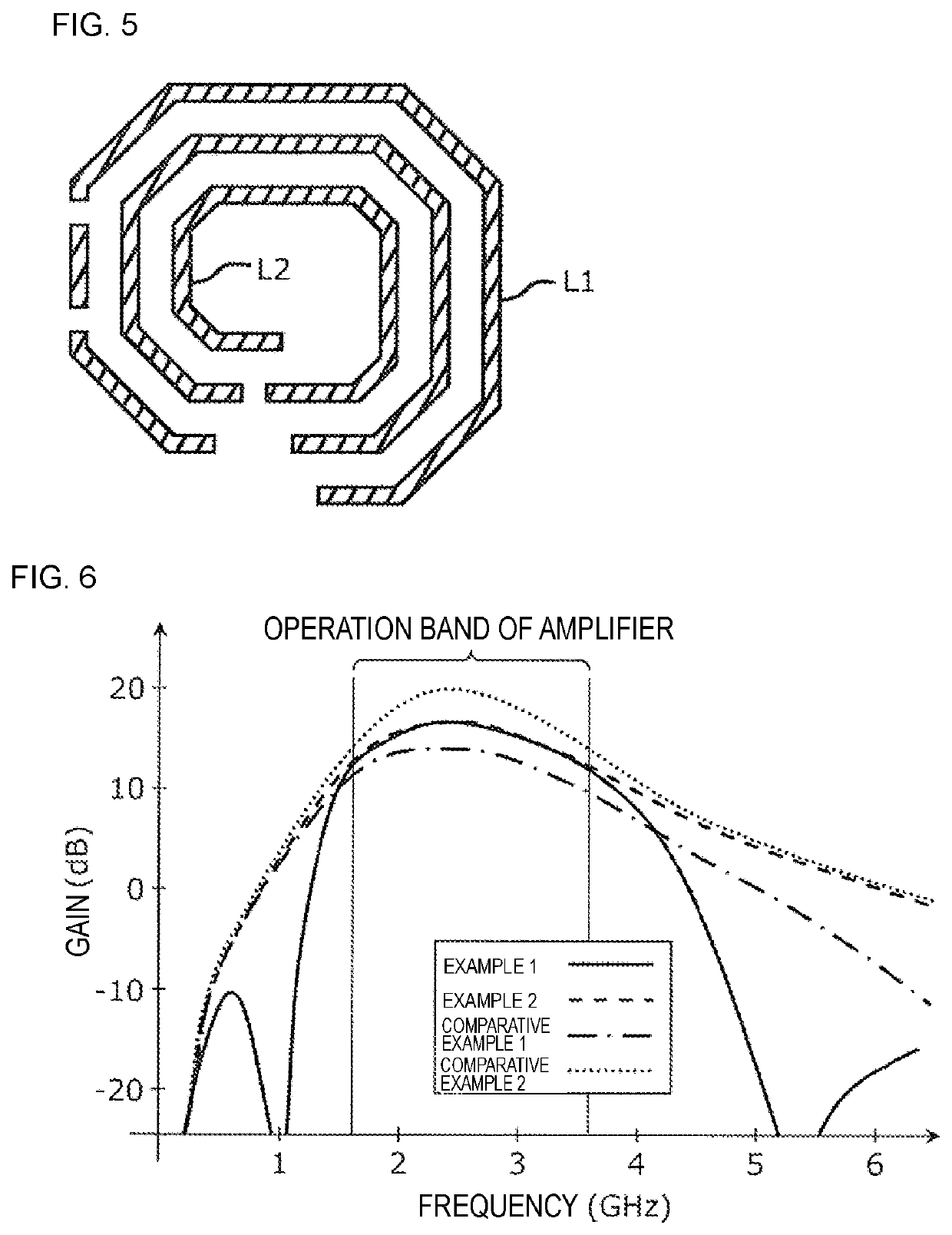
[0058]an amplifying apparatus having the circuit configuration (FIG. 4) of the amplifying apparatus 9, in which the inductors L1 and L2 are arranged so as to overlap each other (FIG. 5).


PUM


Abstract

An amplifying apparatus includes a transistor arranged on a substrate and constituting an amplifier, an input terminal for inputting a high-frequency signal to the amplifier, an output terminal for outputting the high-frequency signal amplified by the amplifier, a first inductor formed in or on the substrate and connected between a source of the transistor and a ground, and a second inductor formed in or on the substrate and connected between a gate of the transistor and the input terminal. When the substrate is viewed in a plan view, the first inductor and the second inductor do not overlap each other. The first inductor and the second inductor are magnetically coupled to each other.

Description

[0001]This application claims priority from Japanese Patent Application No. 2019-088464 filed on May 8, 2019. The content of this application is incorporated herein by reference in its entirety.BACKGROUND OF THE DISCLOSURE1. Field of the Disclosure[0002]The present disclosure relates to an amplifying apparatus.2. Description of the Related Art[0003]A power amplification module for amplifying a radio frequency transmission signal has been used in various communication devices such as a wireless terminal device (for example, see U.S. Patent Application Publication No. 2018 / 0226367).[0004]U.S. Patent Application Publication No. 2018 / 0226367 discloses a low-noise amplification system including an amplifier circuit configured by two amplifiers cascode-connected, and an input matching circuit including a first inductor connected in series to a gate of the amplifier and an inductor connected between the gate of the amplifier and a ground (for example, FIG. 41A in U.S. Patent Application Pu...

Claims


Application Information

Patent Timeline
IPC IPC(8): H03F1/34H03F3/195H03F1/56
CPCH03F2200/451H03F1/565H03F2200/129H03F1/342H03F2200/222H03F2200/294H03F3/195H03F1/223
Inventor TABEI, MAKOTO
Owner MURATA MFG CO LTD
Why Eureka
Try Eureka