Speaker

a technology of speaker and coil, applied in the field of speaker, can solve the problem of low cost of magnet, achieve the linearity of driving force of the coil, reduce the difference in magnetic field strength and its distribution, and reduce the weight

Active Publication Date: 2006-03-02
ALPINE ELECTRONICS INC
View PDF15 Cites 10 Cited by
  • Summary
  • Abstract
  • Description
  • Claims
  • Application Information

AI Technical Summary

Benefits of technology

[0019] According to the present invention, the length of the coil in the moving direction is preferably equal to a distance between peak points of magnetic force strength induced by the first magnetized surface and the second magnetized surface. This distance can easily achieve the linearity of driving force of the coil. Also, for example, the length of the coil in the moving direction is preferably equal to a distance between the center positions of the lengths of the first magnetized surface and the second magnetized surface in the moving direction of the coil. Furthermore, the length of the first magnetized surface is preferably equal to that of the second magnetized surface in the moving direction of the coil.
[0020] The spacing of the gap is preferably constant within the moving range of the coil. Additionally, the magnet is preferably a ring magnet radially polarized and magnetized to reduce the weight.
[0021] According to the present invention, a single magnet can ensure the linearity of driving force of a coil. In addition, a single magnet having two magnetized surfaces reduces the difference in magnetic field strength and its distribution induced by the two magnetized surfaces. Therefore, the linearity of driving force can be easily provided. Also, speakers using this magnet have substantially the same linearity characteristic. Furthermore, using a single magnet can reduce the manufacturing cost of the speaker.

Problems solved by technology

Furthermore, since a single magnet is used, the cost of the magnet is low.

Method used


Image

  • Speaker
  • Speaker
  • Speaker

Examples


Embodiment Construction

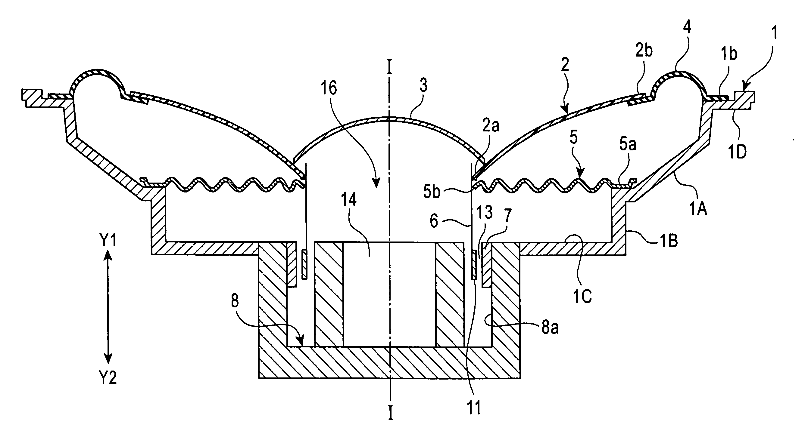
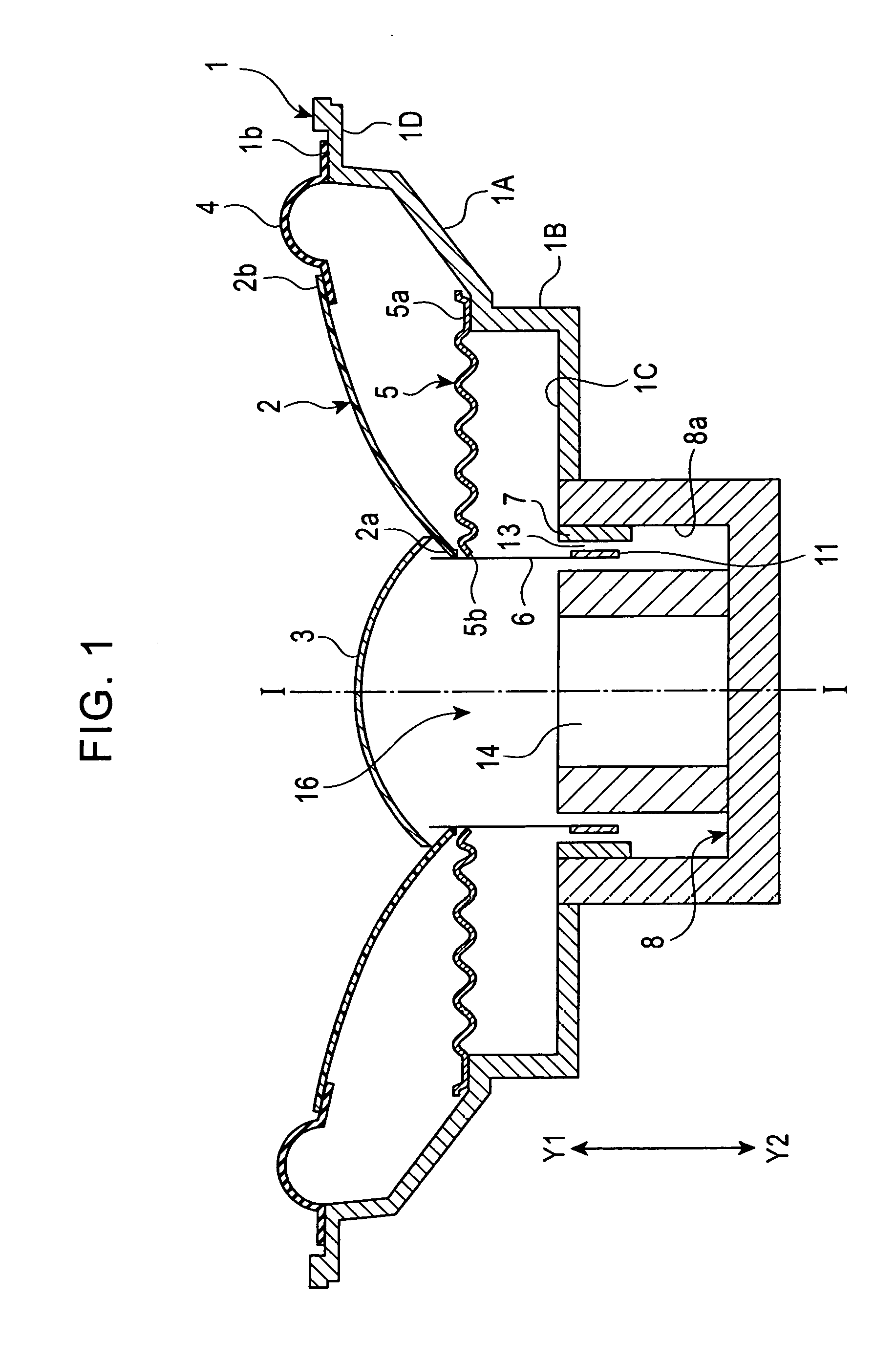
[0027] As shown in FIG. 1, a speaker generally includes a frame 1, a diaphragm 2, and a magnetic driving unit 16. In FIG. 1, a center line (center axis) extending in the direction Y1-Y2, which is a fore and aft direction of the speaker, is shown as a line I-I. The sound output from the speaker travels in the Y1 direction.

[0028] The frame 1 is formed from a nonmagnetic metal material (e.g., an aluminum alloy) by die casting. Alternatively, the frame 1 may be formed from a synthetic resin by injection molding. The frame 1 has a horn shape with an opening in the Y1 direction, and the axis thereof coincides with the center line I-I. The frame 1 includes, in series, a tapered portion 1A whose inner diameter gradually increases towards the Y1 direction, a cylinder portion 1B extending from the small-diameter end of the tapered portion 1A towards the rear of the frame 1 (in the Y2 direction), and a bottom portion 1C connected to the cylinder portion 1B.

[0029] The diaphragm 2 is formed fr...


PUM


Abstract

A speaker includes a magnet, a yoke, and a coil. A surface of the magnet opposed to the yoke includes a first magnetized surface at one side in the moving direction of the coil and a second magnetized surface at the other side in the moving direction of the coil. The two magnetized surfaces have the same magnetic polarity. A central surface between the first magnetized surface and the second magnetized surface is not magnetized or is magnetized more weakly than the first magnetized surface and the second magnetized surface. The single magnet of this structure forms the same magnetic force distribution as two separate magnets so that the speaker provides a superior linearity of driving force of the coil.

Description

BACKGROUND [0001] 1. Field of the Invention [0002] The present invention relates to a speaker including a voice coil driven by a single magnet and, in particular, to a speaker including a voice coil driven by a single magnet and providing the magnetic force distribution and performance identical to that of a speaker using two magnets. [0003] 2. Description of Related Art [0004] In general, a speaker includes a frame, a diaphragm supported by the frame, and a magnetic driving unit. The magnetic driving unit includes a magnet attached to the frame, a magnetic yoke opposed to the magnet, and a coil (voice coil) which is disposed in a gap between the magnet and the opposing magnetic yoke and which moves along with the diaphragm. [0005] In the magnetic driving unit, the coil is driven by an electromagnetic force induced by a magnetic flux emanating from the magnet to the magnetic yoke over the gap and the electrical current flowing in the coil located in the gap. Therefore, the diaphragm...

Claims


Application Information

Patent Timeline
Patent Type & Authority Applications(United States)
IPC IPC(8): H04R25/00
CPCH04R9/025
Inventor SHIMAMURA, NAOKI
Owner ALPINE ELECTRONICS INC
Why Eureka
Try Eureka