Dust collector

a technology for dust collectors and dust collectors, applied in the direction of filtration separation, cleaning filter means, separation processes, etc., can solve the problems of complex structure of dust collectors, and achieve the effect of simple structur

Active Publication Date: 2015-01-27
MAKITA CORP
View PDF4 Cites 1 Cited by
  • Summary
  • Abstract
  • Description
  • Claims
  • Application Information

AI Technical Summary

Benefits of technology

[0006]It is an object of the present invention to provide a dust collector capable of cleaning a filter during operation with a simple structure.
[0012]In the dust collector according to the first aspect of the present invention, the first opening and closing members of the pair of intake paths is alternately caused to perform the closing operation by the operation unit. Thus, dust can be alternately removed from the filters of the pair of intake paths. Accordingly, the filters in the pair of intake paths can be cleaned during the operation of the dust collector as well. Moreover, since the first opening and closing members and the second opening and closing members are operated by the operation unit, electric control is not required to operate the opening and closing members, whereby the structure of the dust collector is simplified.
[0013]In the dust collector according to the second aspect of the present invention, the number of motors and cam members that alternately cause the first opening and closing members to perform the closing operation can be minimized. This can suppress manufacturing cost of the dust collector.
[0014]In the dust collector according to the third aspect of the present invention, the filters through which air flows in the pair of intake paths can be arranged in the tank so as not to interfere with the motor and the first opening and closing members, so that longitudinal dimension of the tank can be suppressed.
[0015]In the dust collector according to the fourth aspect of the present invention, accumulation of static electricity on the primary filter can be suppressed. This suppresses electrostatic attraction of dust to the primary filter, whereby satisfactory dust separation from the filter can be achieved.

Problems solved by technology

However, since the above dust collector uses the electromagnetic valves to open and close the air inlet pipes, a device that electrically controls electromagnets that drive the electromagnetic valves is required, which may complicate the structure of the dust collector.

Method used


Image

  • Dust collector
  • Dust collector
  • Dust collector

Examples


Embodiment Construction

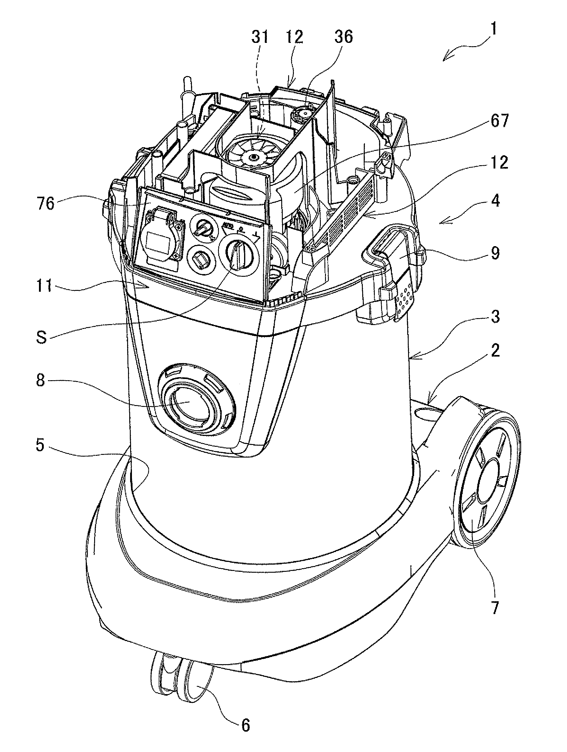
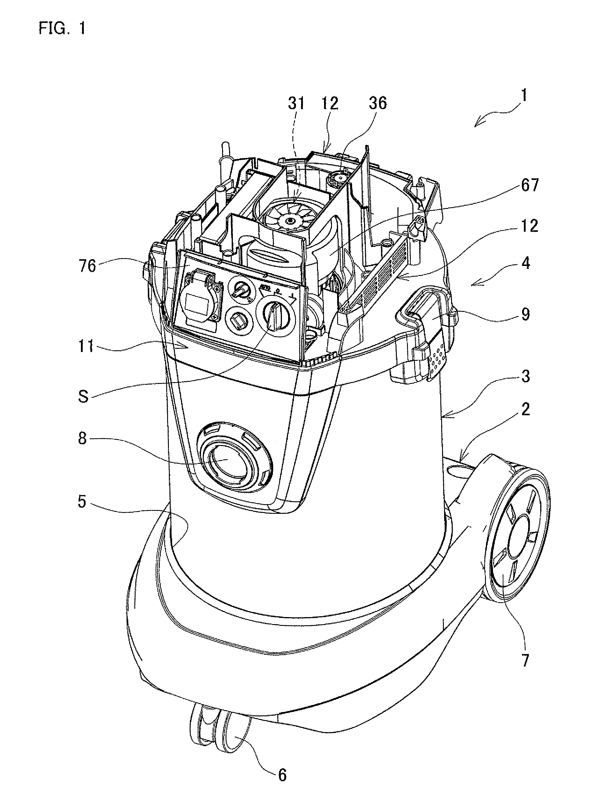
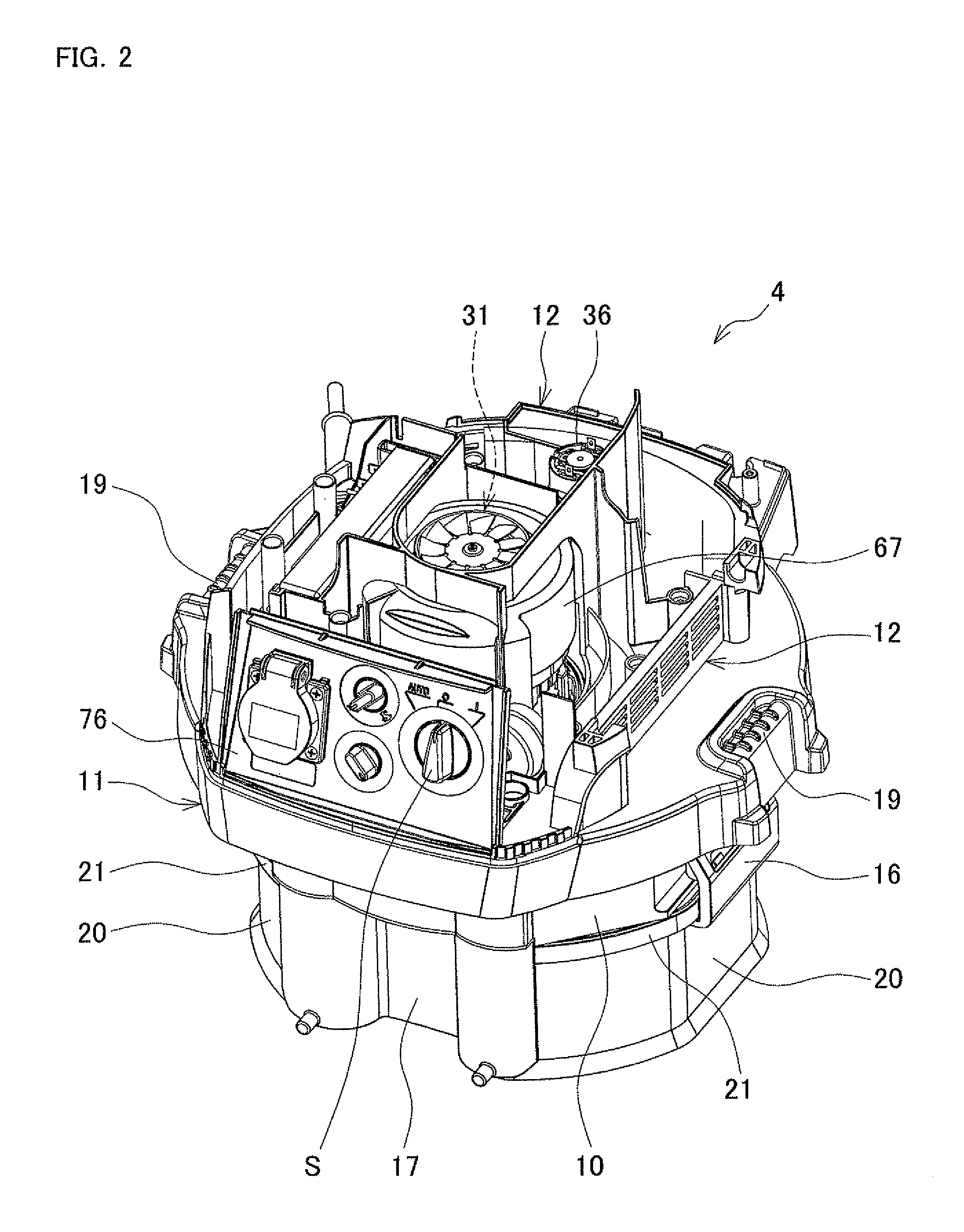
[0029]An embodiment of the present invention will be described with reference to FIGS. 1 to 11. As shown in FIGS. 1 to 3, a dust collector 1 includes a traveling base 2, a tank 3, and a main body 4. The traveling base 2 is molded by using a synthetic resin, and has a circular recess 5 (see FIG. 1) in the upper surface thereof. One front wheel 6 is rotatably provided on a front (the side closer to the viewer in FIG. 1) central part of the bottom surface of the traveling base 2, and a pair of rear wheels 7, 7 are rotatably provided on the rear (the side away from the viewer in FIG. 1) left and right parts of the traveling base 2. The dust collector 1 is capable of traveling by the front wheel 6 and the rear wheels 7, 7.

[0030]The tank 3 is made of stainless steel, and is formed to have a bottomed cylindrical shape opening in its upper part. The tank 3 is placed on the upper surface of the traveling base 2 so as to be fitted in the recess 5. A suction port 8 is formed in the front surfa...


PUM

PropertyMeasurementUnit
rotationaaaaaaaaaa
pressureaaaaaaaaaa
suctionaaaaaaaaaa

Abstract

A dust collector having a filter for catching dust in air flowing in an intake path is provided. A pair of the intake paths are formed so as to be combined together on an upstream side of an electric blower provided in a main body. A pair of communication paths allow a discharge passage to communicate with each of the intake paths. A first opening and closing member is provided so as to open and close the intake path, and in a normal state, is biased to open the intake path. A second opening and closing member is provided so as to open and close the communication path, and in the normal state, is biased to close the communication path, and opens the communication path in response to a closing operation of the intake path by the first opening and closing member.

Description

BACKGROUND OF THE INVENTION[0001]This application claims the benefit of Japanese Patent Application Number 2011-278506 filed on Dec. 20, 2011, the entirety of which is incorporated by reference.TECHNICAL FIELD[0002]The present invention relates to dust collectors that include, in an upper part of a tank having a suction port, a main body having an electric blower, and that draw air through the suction port from outside by the electric blower, and catch dust in the air by a filter provided in the tank.BACKGROUND ART[0003]For example, Japanese Patent No. 3,457,929 discloses a dust collector in which a filter group separating a gas inlet of a dust container from a gas outlet thereof is contained in the dust container having a hermetically sealed structure, air and dust are drawn through the gas inlet into the dust container having a negative pressure due to evacuation from the gas outlet, and the dust is captured by the filter group. This dust collector is provided with a plurality of ...

Claims


Application Information

Patent Timeline
Patent Type & Authority Patents(United States)
IPC IPC(8): B01D41/00A47L5/28A47L9/20B01D46/00
CPCB01D46/0068A47L5/28A47L9/20B01D46/71
Inventor HARA, RYOSUKETAHARA, TAKAYUKI
Owner MAKITA CORP
Why Eureka
Try Eureka