Image projection apparatus

a projection apparatus and image technology, applied in the field can solve the problems of inability to obtain satisfactory image quality, affecting the quality of image projection apparatuses, and prone to reflection at the interface of field lenses, etc., and achieve the effect of satisfying separation

Inactive Publication Date: 2008-10-14
KONICA MINOLTA OPTO
View PDF14 Cites 0 Cited by
  • Summary
  • Abstract
  • Description
  • Claims
  • Application Information

AI Technical Summary

Benefits of technology

[0011]In view of the conventionally experienced disadvantages discussed above, it is an object of the present invention to provide an image projection apparatus that achieves satisfactory separation between illumination light and projection light without the use of a field lens or a TIR prism.
[0021]In the image projection apparatus constructed as described above, the deflection axis of the pixels of the display device is made to run parallel to the longer sides of the display area of the display device. This helps direct the illumination light and the projection light in directions perpendicular to the longer sides of the display area. In addition, the entrance pupil of the projection optical system is disposed in the direction parallel to the shorter sides of the display area (that is, in the direction perpendicular to the longer sides thereof). This helps increase the degree of deflection of the projection light relative to the illumination light, and thus helps achieve improved separation between the illumination light and the projection light.
[0022]Conditional formula (i) defines the condition to be fulfilled to achieve separation between the illumination light and the projection light, and therefore fulfilling it results in superb separation between the illumination light and the projection light. On the other hand, fulfilling conditional formula (ii) helps increase the numerical apertures of the illumination light traveling from the illumination optical system to the display device and of the projection light traveling from the display device to the projection optical system. This helps achieve satisfactory energy transmission efficiency between the two optical systems.

Problems solved by technology

Image projection apparatuses provided with a field lens, however, are prone to suffer from reflection at the interfaces of the field lens.
Such reflection causes ghosts and diminishes contrast.
Thus, with these image projection apparatuses, it is impossible to obtain satisfactory image quality.
These image projection apparatuses, however, are expensive just because the TIR prism itself is expensive.
In addition, these image projection apparatuses suffer from a significant loss of light at the air gap surfaces of the TIR prism.

Method used


Image

  • Image projection apparatus
  • Image projection apparatus
  • Image projection apparatus

Examples


first embodiment

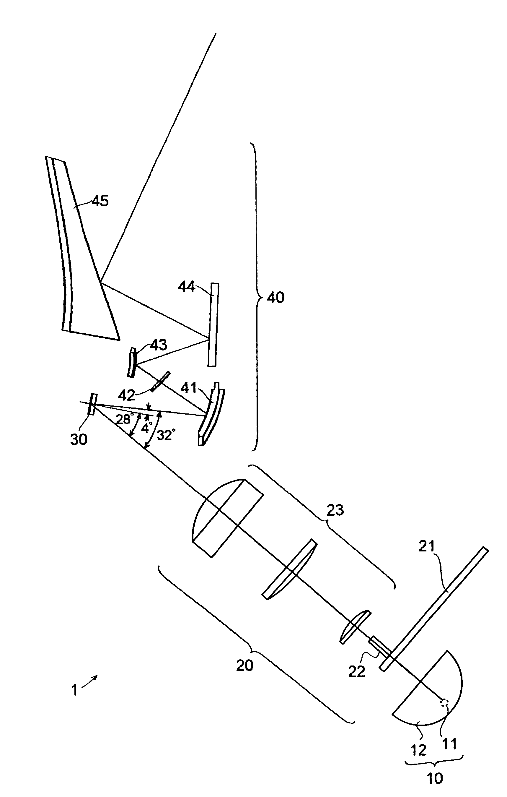
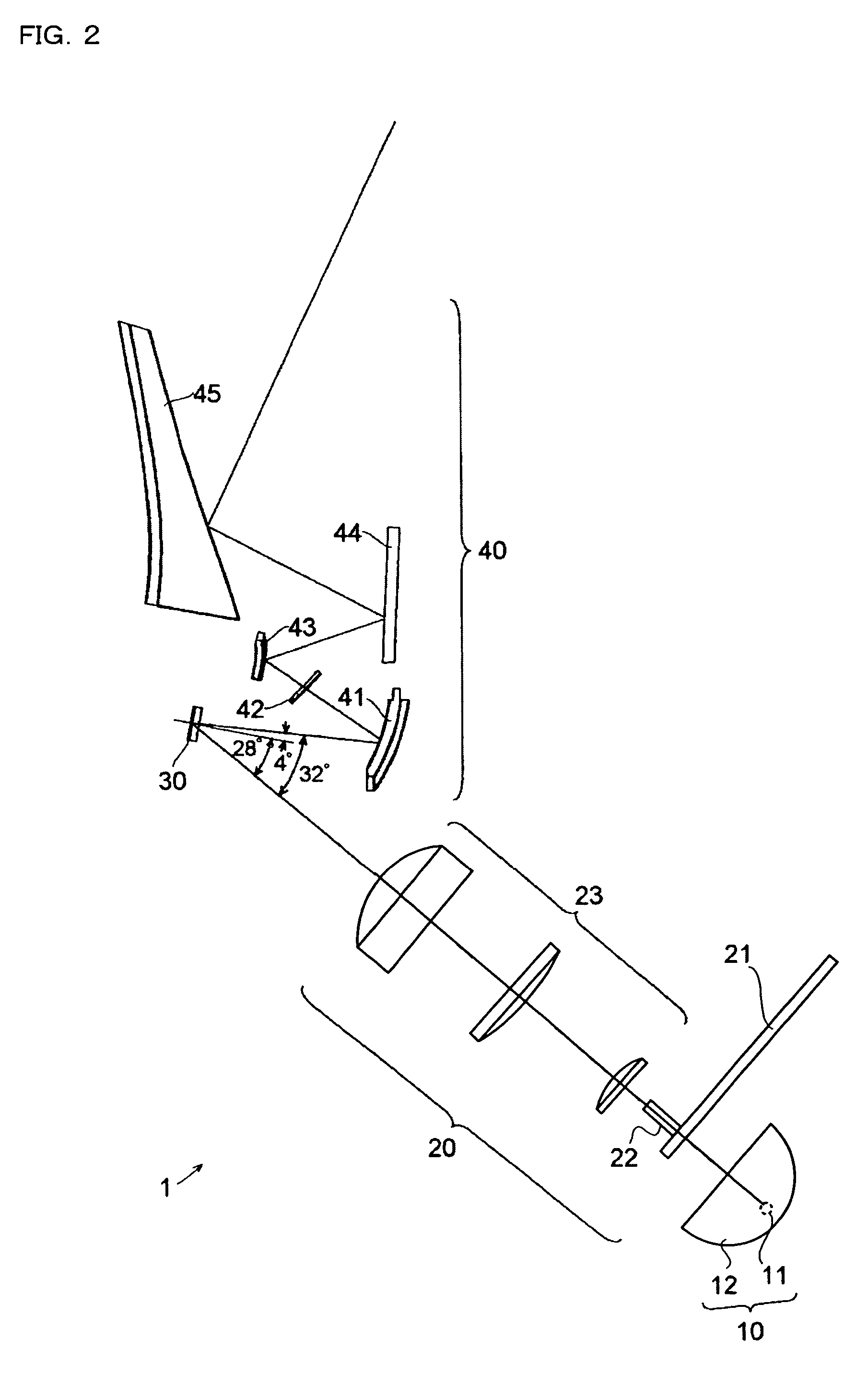
[0036]Hereinafter, embodiments of the present invention will be described with reference to the drawings. FIG. 1 shows the overall optical construction of the image projection apparatus 1 of a first embodiment of the invention. FIG. 2 shows the optical construction of a principal portion of the image projection apparatus 1 of the first embodiment.

[0037]The image projection apparatus 1 of this embodiment is provided with a light source 10, an illumination optical system 20, a reflective display device 30, a projection optical system 40, and a screen 50.

[0038]The light source 10 includes: a lamp 11 that emits white light; and a reflector 12 that has a surface in the shape of an ellipsoid of revolution. The light source 10 emits illumination light for illuminating the display device 30.

[0039]The lamp 11 is disposed at the first focus of the reflector 12, and thus the light emitted from the lamp 11 is reflected from the reflector 12 so as to converge at the second focus thereof.

[0040]Th...

second embodiment

[0096]A second embodiment of the present invention will be described below. As described above, in the image projection apparatus 1 of the first embodiment, of the light reflected from each pixel in two different direction (see FIG. 3), that so reflected as to form the smaller angle relative to the illumination light is used as the projection light, and that so reflected as to form the larger angle is handled as unnecessary light. With this design, however, diminished contrast may result because of the pixels that produce unnecessary light.

[0097]Why this happens is illustrated in FIG. 8A. FIG. 8A shows a group of contiguously located pixels 31 producing unnecessary light. When producing unnecessary light, the pixels 31 are oriented closer to parallel to the illumination light. As a result, as shown in FIG. 8A, if a group of contiguously located pixels 31 produce unnecessary light, part of the illumination light passes between the pixels 31.

[0098]The illumination light that has passe...


PUM


Abstract

In an image projection apparatus, the deflection axis of the pixels of a display device is parallel to the longer sides of the display area of the display device, and the entrance pupil of a projection optical system is displaced from the line normal to the center of the display area in the direction parallel to the shorter sides of the display device. The distance from the display device to the optical component closest thereto is determined based on the intersection between the lowermost ray of projection light that leaves the lower end of the display area and reaches the entrance pupil of the projection optical system and the uppermost ray of illumination light that leaves the illumination optical system and reaches the upper end of the display device.

Description

[0001]This application is based on Japanese Patent Application No. 2004-253716 filed on Sep. 1, 2004 and Japanese Patent Application No. 2005-236612 filed on Aug. 17, 2005, the contents of which are hereby incorporated by reference.BACKGROUND OF THE INVENTION[0002]1. Field of the Invention[0003]The present invention relates to an image projection apparatus that displays an image and then projects it, and more particularly to an image projection apparatus employing a reflective display device that displays an image through angle modulation of pixels.[0004]2. Description of Related Art[0005]Many image projection apparatuses use a reflective display device that displays an image through angle modulation of pixels. Such an image projection apparatus is provided with an illumination optical system for directing illumination light to the display device and a projection optical system for projecting image light (that is, light representing an image) from the display device.[0006]Here, the ...

Claims


Application Information

Patent Timeline
Patent Type & Authority Patents(United States)
IPC IPC(8): G03B21/28
CPCG03B21/14G03B21/28G03B21/62H04N5/7408H04N9/3114H04N9/315G03B21/208
Inventor SAWAI, YASUMASAKUWA, TOMIEI
Owner KONICA MINOLTA OPTO
Why Eureka
Try Eureka