Energy recovery high efficiency dehumidification system

a dehumidification system and energy recovery technology, applied in space heating and ventilation, lighting and heating apparatus, heating types, etc., can solve the problems of insufficient and poorly designed cooling, inconvenient use, and inability to meet the needs of users, and achieve high efficiency and mold growth. the effect of high efficiency

Active Publication Date: 2022-05-17
HEDS HLDG LLC
View PDF133 Cites 2 Cited by
  • Summary
  • Abstract
  • Description
  • Claims
  • Application Information

AI Technical Summary

Benefits of technology

[0006]Various embodiments of the present subject matter provide for an Energy Recovery High Efficiency Dehumidification System (ERHEDS) and in some instances, a one-hundred-percent Energy Recovery High Efficiency Dehumidification System (100% ERHEDS). With the ERHEDS, mold growth can be eliminated, and climate control can be provided with the use of fewer resources. That is, the system provides for reduced life cycle cost (in energy usage, water usage and maintenance), it is easy to configure and scale, and provides more reliable / resilient systems for controlling the climate within an enclosed facility. The ERHEDS system can be utilized in facilities that are unoccupied, or in need of rapid dehumidification. In some embodiments, the ERHEDS can transition functions and be utilized to control the conditions in occupied facilities such as ships, residential homes, military barracks, commercial, industrial and institutional facilities, Municipal, University, State and Hospital facilities, clean rooms, laboratories, and even greenhouses for plant material such as cannabis grow houses.
[0007]In some aspects, an energy recovery high efficiency dehumidification system for providing hot air or hot dehumidified air to a facility can include an air filter bank, a supply fan, a preheat coil, a cooling coil, a chemical or biological mitigation system, a cooling recovery coil, an equipment room, and / or a heat rejection coil, and / or the like. The air filter bank can receive air from a first inlet source. The supply fan can cause the air to flow from the first inlet source. The cooling coil can cool and reduce a relative humidity of the air that passes over the cooling coil. The cooling recovery coil can be coupled with the cooling coil and can heat the cooled air to generate cooled dehumidified reheated air in a cooling recovery coil plenum. The equipment room can surround mechanical and electrical equipment and receive the cooled dehumidified reheated air from the cooling recovery coil plenum. The cooled dehumidified reheated air is configured to be further heated. The heat rejection coil that rejects heat recovered from one or more components of the mechanical and electrical equipment and cooling equipment can cause a temperature of the further heated cooled dehumidified reheated air to increase. The air can pass through an outlet to other HVAC equipment, or to the facility or process load.
[0008]In some aspects, an energy recovery high efficiency dehumidification system for providing cool dehumidified air to a facility can include an air filter bank, a supply fan, a preheat coil, a cooling coil, a chemical or biological mitigation system, a cooling recovery coil, a first outlet, an equipment room and / or a heat rejection coil, among other components. The air filter bank can receive outside air from an environment via a first inlet source. The supply fan can cause the air to flow from the first inlet source. The cooling coil can cool and reduce the moisture content of the air that passes over the cooling coil. The cooling recovery coil can be coupled with the cooling coil and configured to heat the cooled air to generate cooled dehumidified reheated air in a cooling recovery coil plenum. The first outlet can be coupled with ductwork to allow the cooled dehumidified reheated air to pass to a facility. The equipment room can surround mechanical and electrical equipment and receive outside air from an environment via a second inlet source. The outside air entering the equipment room can be heated. The heat rejection coil can reject heat recovered from one or more components of the mechanical and electrical equipment and cooling equipment to cause a temperature of the heated outside air to increase. The heated outside air can pass through an outlet to the environment.

Problems solved by technology

Common problems created by industry standard cooling coil, cooling unit, cooling systems, and HVAC designs include, but are not limited to: high airside pressure drop; excessive cooling coil vertical height that creates a condensate “stacking” effect; inadequate numbers of coil rows can create a condensate stacking effect; inadequate and poorly designed cooling coil drain pans; excessive air velocity across the coil sections during deep dehumidification duties; excessive liquid water (condensate) being carried off of the coil into the unit and downstream ductwork; condensate carry-off being re-evaporated into the airstream; condensate being carried off and re-evaporated off of the cooling coil and drain pan systems due to compressor cycling on and off; condensate being carried off and re-evaporated off of the cooling coil and drain pan systems due to temperature swings; inability to unload far enough to provide proper temperature and relative humidity (RH) control when loads are light; energy waste, excessive water, and chemical consumption; excessive energy rejection to, or withdrawal from, ground coupled HVAC systems; undersized ductwork and air distribution terminal units; and other common system design and operational problems, as described in more detail herein.

Method used


Image

  • Energy recovery high efficiency dehumidification system
  • Energy recovery high efficiency dehumidification system
  • Energy recovery high efficiency dehumidification system

Examples


Embodiment Construction

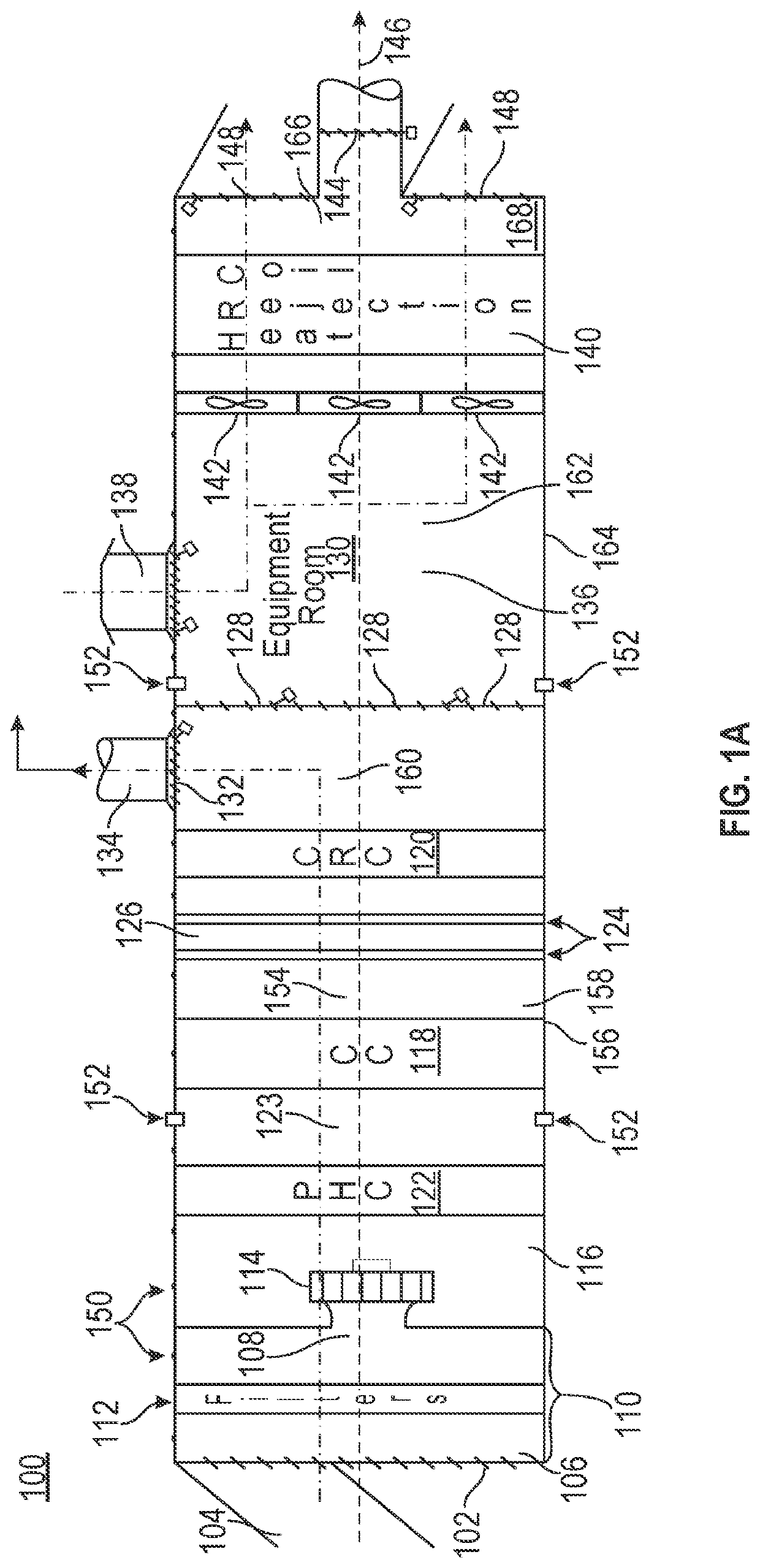
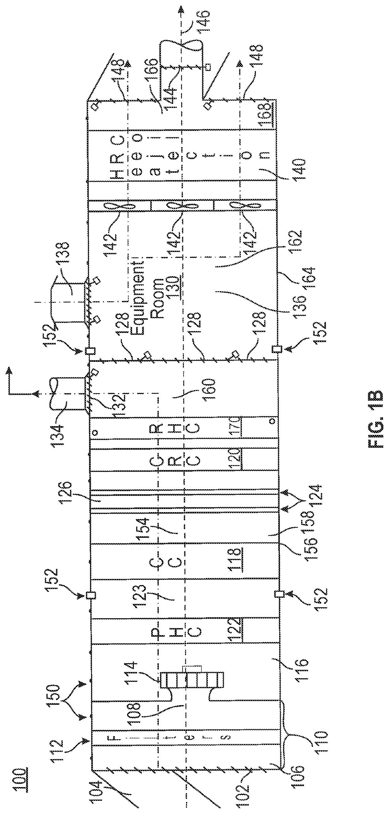
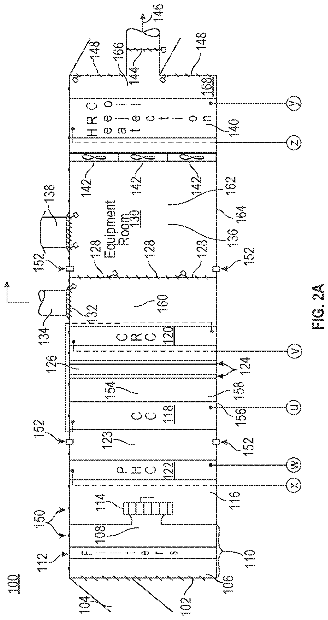
[0020]While the present technology is susceptible of embodiment in many different forms, there is shown in the drawings and will herein be described in detail several specific embodiments with the understanding that the present disclosure is to be considered as an exemplification of the principles of the present technology and is not intended to limit the technology to the embodiments illustrated.

[0021]It will be understood that like or analogous elements and / or components, referred to herein, may be identified throughout the drawings with like reference characters. It will be further understood that several of the figures are merely schematic representations of the present subject matter. As such, some of the components may have been distorted from their actual scale for pictorial clarity.

[0022]When a feature or element is herein referred to as being “on” another feature or element, it can be directly on the other feature or element or intervening features and / or elements may also ...


PUM


Abstract

Disclosed herein are systems and methods for providing hot air or hot dehumidified air to a facility using an energy recovery high efficiency dehumidification system. The energy recovery high efficiency dehumidification system can include an air filter bank that receives air from a first inlet source, a supply fan that causes the air to flow from the first inlet source, a cooling coil configured to cool and reduce a relative humidity of the air that passes over the cooling coil, a cooling recovery coil coupled with the cooling coil and configured to heat the cooled air to generate cooled dehumidified reheated air in a cooling recovery coil plenum, an equipment room configured to surround mechanical and electrical equipment and further heat received cooled dehumidified reheated air, and a heat rejection coil that rejects heat from one or more components of the mechanical and electrical equipment to further heat the air.

Description

CROSS-REFERENCE TO RELATED APPLICATIONS[0001]This application claims the benefit of U.S. Provisional Application No. 62 / 641,200, filed Mar. 9, 2018, and U.S. Provisional Application No. 62 / 641,211, filed Mar. 9, 2018, the disclosures of which is hereby incorporated by reference. This application is also related to U.S. application Ser. No. 16 / 234,023, filed Dec. 27, 2018. The disclosures of the above-reference applications are hereby incorporated by reference in their entirety for all purposes.TECHNICAL FIELD[0002]The present subject matter pertains to climate control systems. In particular, but not by way of limitation, the present subject matter provides for energy efficient climate control systems.BACKGROUND OF THE INVENTION[0003]Existing coil and dehumidification unit designs commonly implemented for cooling, dehumidification and reheat duties have a number of drawbacks.[0004]Common problems created by industry standard cooling coil, cooling unit, cooling systems, and HVAC desig...

Claims


Application Information

Patent Timeline
Patent Type & Authority Patents(United States)
IPC IPC(8): F24F3/153F24F3/16F24F13/15F24F13/14F24F8/10F24F8/22
CPCF24F3/153F24F8/10F24F13/1413F24F13/15F24F8/22
Inventor DUNCAN, SCOT MATTHEW
Owner HEDS HLDG LLC
Why Eureka
Try Eureka