Kiteboard

a technology of kiteboards and boards, applied in the field of kiteboards, can solve the problems of difficult assembly of boards known from the prior art, high demand for storage space and transportation space, and non-practical transportation, etc., and achieve the effect of convenient storage and transportation

Active Publication Date: 2022-05-24
ISEINOSKI ALEXANDER
View PDF13 Cites 0 Cited by
  • Summary
  • Abstract
  • Description
  • Claims
  • Application Information

AI Technical Summary

Benefits of technology

[0009]It is an object of the invention to provide a kiteboard, which is adaptable to a wide range of different conditions. A further object of the invention is to provide a board which can be easily stored and transported in a space-saving way.
[0011]By combining the base with different front and / or back extensions the width (in a lateral direction) and / or the length (in a longitudinal direction) of the overall kiteboard may be adjusted. Hence, a modular setup can be arranged with a fully functional base and one or several front and back extension. One base can be interconnected with one or several front and back extensions via the first and the second mechanical interface thereby covering the full spectrum of different applications of a kiteboard. Thus, for each user an individual a kit may be provided comprising a base and at least two front extensions and / or at least two back extensions such that a user can exchange the front and / or back extension to generate different kiteboards with different performance characteristics. In some applications, the base may thereby be a fully functioning kiteboard in itself. In the situation where the base acts as a kiteboard, the outer edge face of the base, respectively transition region of the outer edge face and the bottom face of the base are developed as a so called riding edge which, during riding, is actively taking influence on the riding behavior as it interacts with the water surrounding the kiteboard. In this case the edge acts as flow breakaway edge. Thus, a riding edge is preferably optimized fluid-mechanically as well as in terms of the structural properties since a riding edge experiences a stronger wear than e.g. the top face of a kiteboard. Therefore the edges of kiteboards, respectively the riding edges, are usually strengthened. This may be done e.g. by turning over the fibers at the edge of a fiber reinforced board such that no ends of fiber layers are exposed at the outer edge face and / or by using reinforcing fill materials at the edges. Additionally or alternatively, the riding edge may comprise a reinforcing element, preferably a reinforcing strip which in placed on and thus reinforces the outer edge face. The reinforcing element may e.g. be made from ABS-plastic. If the base can be used as a kiteboard, the base may represent a narrow kiteboard board which is known to be faster than a wider board. A kiteboard with a greater width can be generated by combining the base with a front and / or a back extension which is results in more stable driving characteristics. Preferably, the width of the base is between WB=0.26-0.38 m such that is may be used without front or back extensions. Advantageously, the width of the kiteboard can then be extended up to WK=0.5 m in various steps by using different front and / or back extensions. Depending on the application the length of the base may be changed together with the width or independently.
[0015]For an advantageous fluidic design, the bottom face of the front extension and / or the back extension in the assembled position continuously merges into the bottom face of the base. Thus, if the kiteboard is moved over the water surface, the drag is minimized due to a smooth surface with no abrupt gradients in the bottom face due to the interconnection of the base to the front and / or back extension.
[0017]In a preferred variation of the invention, the at least one first locking element comprises a tension element, at least two deflecting members and one cord. Hereby, the cord is wound around the at least two deflecting members and the tension element tightens the chord around said deflecting members. The deflecting member deflects the cord in a way that a deflection angle is generated between the incoming cord and the outgoing part of the cord at the deflecting member. Preferably, the deflecting member features therefore a guiding indentation such that the chord is prevented from slipping of. In one variation, the tension element may also deflect the chord. The advantage of this arrangement is the easy handling and the possibility to assemble different combinations. A further advantage is the low profile arrangement which does not significantly stick above the top surface of the board.
[0018]If the parts which shall be interconnected are engaged by means of the first and the second mechanical interface (pre-assembled position), the cord is wound around the respective deflecting members and tensioned by the tension element. For an easy storage of the cord it is further advantageous, if the tension member comprises a feeder roll wish can stash excessive cord and / or the cord over the full cord length if the cord is not in use.

Problems solved by technology

Next to being expensive, this has the disadvantage of a high demand of storage space as well as transportation space, if various boards need to be brought along to the water side due to unknown weather and water conditions.
The boards known from the prior art are difficult to assemble and non-practical for easy transportation.

Method used


Image

  • Kiteboard
  • Kiteboard
  • Kiteboard

Examples


Embodiment Construction

[0031]Reference will now be made in detail to certain embodiments, examples of which are illustrated in the accompanying drawings, in which some, but not all features are shown. Indeed, embodiments disclosed herein may be embodied in many different forms and should not be understood as limited to the embodiments set forth herein; rather, these embodiments are provided so that this disclosure will satisfy applicable legal requirements. Whenever possible, like reference numbers will be used to refer to like components or parts.

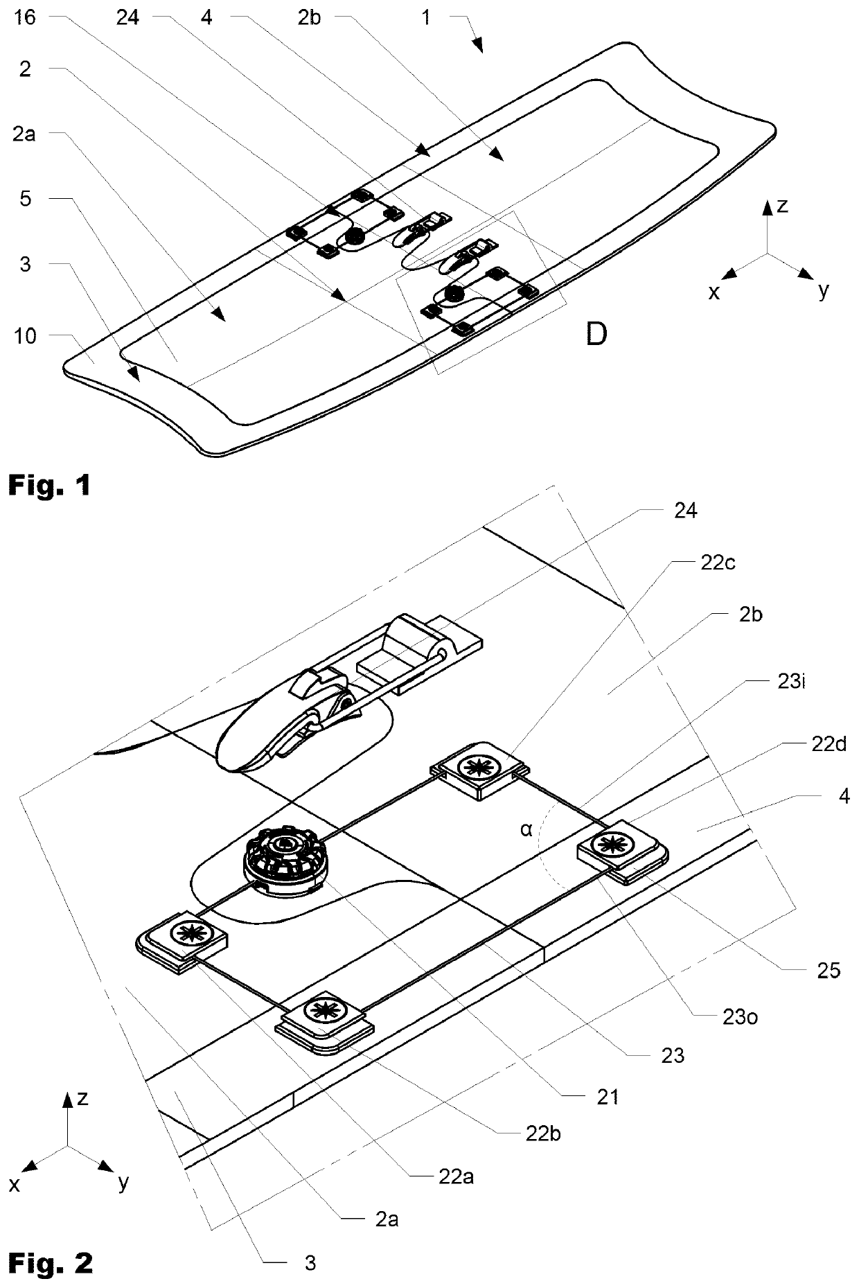
[0032]FIG. 1 shows a first variation of the kiteboard 1 according to the invention in a perspective view and in the assembled position from above. The shown kiteboard 1 comprises a base 2, a front extension 3 and a back extension 4 such that the front extension 3 and the back extension extend around the base 2 and meet each other at a widest area (in the lateral direction y) of the base 2. It can further be seen that in the shown variation the base 2 may be divi...


PUM


Abstract

A kiteboard includes a base, a front extension and / or a back extension. The base includes a top face and a bottom face and an outer edge face. The outer edge face is extending in a circumferential direction along an outer contour of the top face and the bottom face and includes a first mechanical interface. The front extension and / or the back extension include a top face and a bottom face and an inner edge face. The inner edge face extends between the top face and the bottom face along an inner contour and corresponds at least partially to the outer contour of the base. The inner edge face further includes a second mechanical interface, such that in an assembled position the first and the second mechanical inter-face are engaged with each other to position the front extension and / or the back extension with respect to the base.

Description

BACKGROUND OF THE INVENTIONField of the Invention[0001]The present invention relates to a kiteboard according to the patent claims.Discussion of Related Art[0002]Performance characteristics of kiteboards can vary widely depending on the shape of the board, the weather and water conditions. Thus, most users own various kiteboards with different performance characteristics to compensate these effects. Next to being expensive, this has the disadvantage of a high demand of storage space as well as transportation space, if various boards need to be brought along to the water side due to unknown weather and water conditions.[0003]Water boards, such as e.g. surfboards, sail or paddle boards with different configurations, are known. In the following some examples shall be given on adaptable water boards known from the prior art.[0004]U.S. Pat. No. 9,650,114, published on the 16, May 2017 by Maresh Joseph, relates to a modular floating board. The modular floating board has a nose module, a t...

Claims


Application Information

Patent Timeline
Patent Type & Authority Patents(United States)
IPC IPC(8): B63B32/40B63B32/53
CPCB63B32/40B63B32/53
Inventor EGGER, JÖRGISEINOSKI, ALEXANDER
Owner ISEINOSKI ALEXANDER
Why Eureka
Try Eureka