Supercharge Your Innovation With Domain-Expert AI Agents!

System and method for eliminating the presence of droplets in a heat exchanger

a technology of droplets and heat exchangers, which is applied in the direction of steam engine plants, superheating control, lighting and heating apparatus, etc., can solve the problems of not completely dry gas in the steam engine, shorten the life of the turbine, and the sensor arrangement appears not to be adapted for use in the heat exchanger, so as to eliminate the presence of droplets

Active Publication Date: 2022-06-14
CLIMEON AB
View PDF19 Cites 0 Cited by
  • Summary
  • Abstract
  • Description
  • Claims
  • Application Information

AI Technical Summary

Benefits of technology

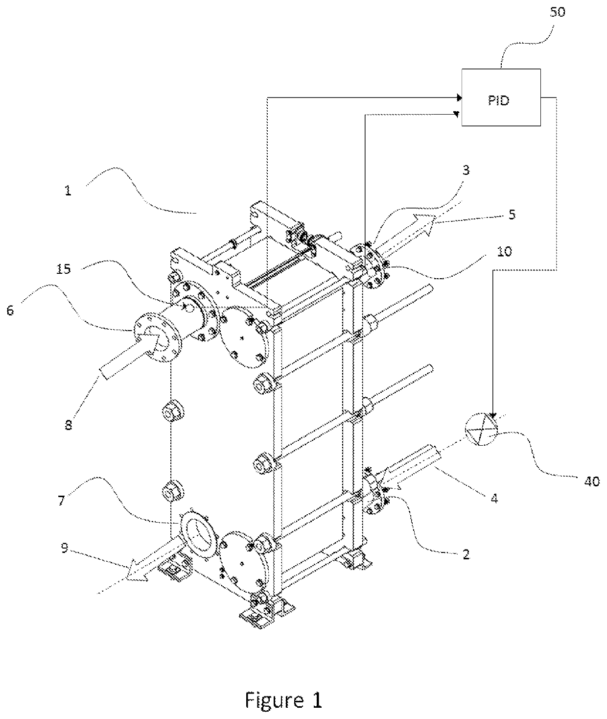
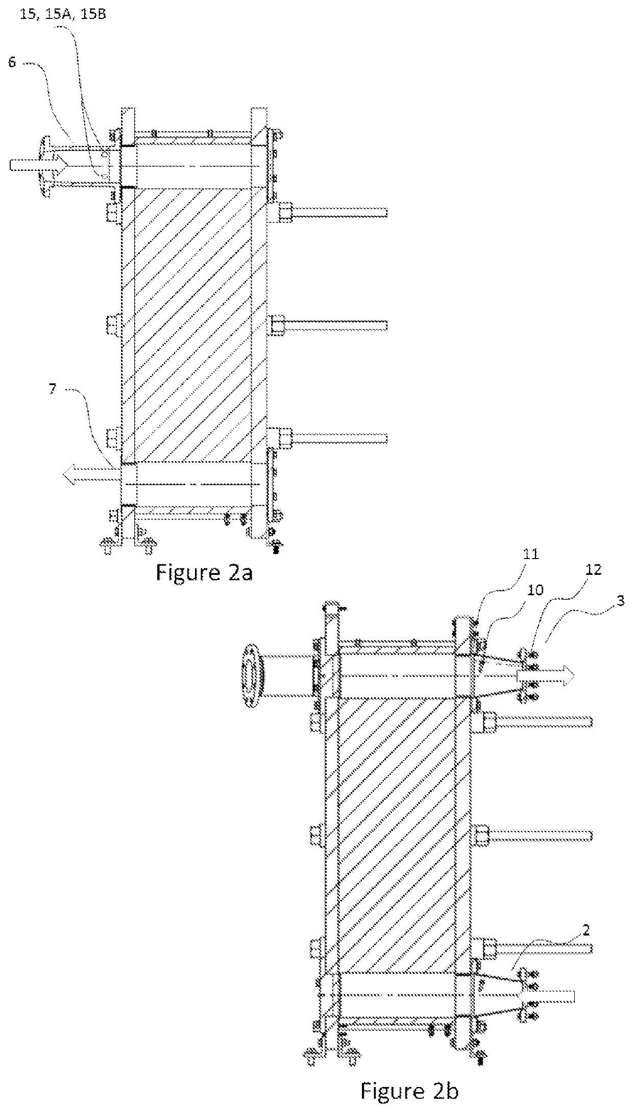
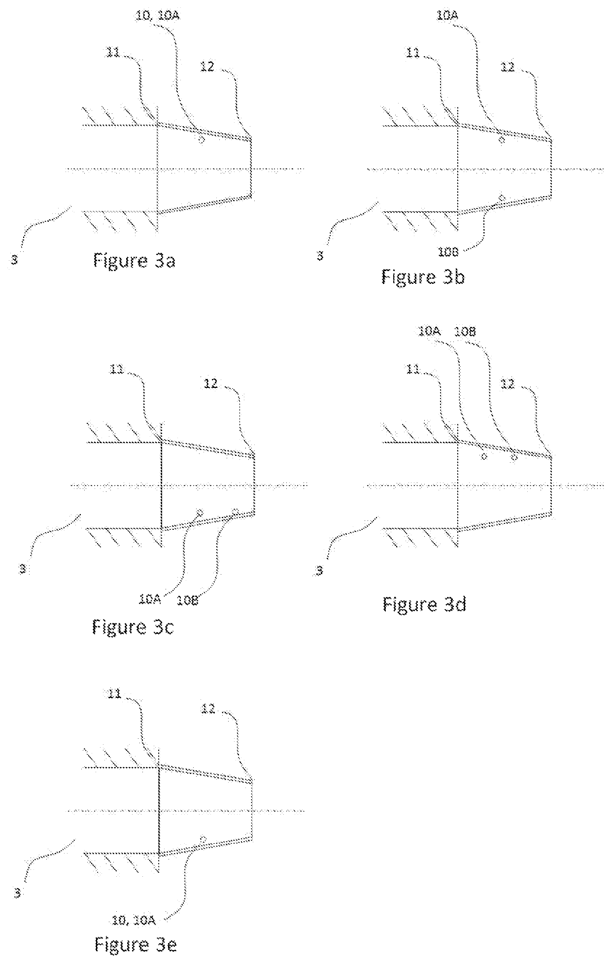
[0008]The first object of the invention is to provide a system and method for eliminating the presence of droplets in a heat exchanger.
[0009]A further object of the invention is to provide a system and method for eliminating the presence of droplets in a heat exchanger which is not dependent on the measurement of pressure.
[0010]A further object of the invention is to provide a system and method for eliminating the presence of droplets in a heat exchanger which is adapted to be used in together with a turbine.

Problems solved by technology

A problem which often arises in power plants is that the gas in not wholly dry, i.e. there are liquid droplets in the gas.
The momentum of fast moving liquid droplets exiting from a heat exchanger damages turbine blades and shortens the life of the turbine.
A similar problem occurs with compressors which are coupled to heat exchangers, i.e. water droplets damage the compressor.
Hence, the sensor arrangement appears not to be adapted for use in a heat exchanger which is used as a boiler.
Additionally, in the system described in EP2674697, the temperature of the second medium (i.e. the medium which transfers heat to the first medium which is to be evaporated) is not measured which results in less accurate and / or precise detection of droplets in the outlet port of the first medium.
However, a droplet separator takes up space in the system, and moreover, is an additional cost which makes the system more expensive.

Method used


Image

  • System and method for eliminating the presence of droplets in a heat exchanger
  • System and method for eliminating the presence of droplets in a heat exchanger
  • System and method for eliminating the presence of droplets in a heat exchanger

Examples


example 2

[0098]The embodiments of Example 2 differ from the embodiments of Example 1 in that the system and method is applied in a heat exchanger which is a plate-and-shell heat exchanger which combines plate heat exchanger with shell and tube heat exchanger technologies.

example 3

[0099]The embodiments of Example 3 differ from the embodiments of Example 1 in that the system and method is applied in a heat exchanger which is a plate-fin heat exchanger, i.e. a heat exchanger which comprises plates and finned chambers to transfer heat between the first medium and the second medium. A plate-fin heat exchanger is made of layers of corrugated sheets separated by flat metal plates to create a series of finned chambers. Separate hot and cold fluid (i.e. second and first media) streams flow through alternating layers of the heat exchanger and are enclosed at the edges by side bars. Heat is transferred from one stream through the fin interface to the separator plate and through the next set of fins into the adjacent fluid / medium. The fins also serve to increase the structural integrity of the heat exchanger and allow it to withstand high pressures while providing an extended surface area for heat transfer.

example 4

[0100]The embodiments of Example 4 differ from the embodiments of Example 1 in that the system and method is applied in a heat exchanger which is a shell-and-tube heat exchanger. A shell-and-tube heat exchanger comprises a shell (i.e. a large pressure vessel) with a bundle of tubes (i.e. pipes) inside it. One fluid (e.g. first medium) runs through the tubes, and another fluid (e.g. the second medium) flows over the tubes (through the shell) to transfer heat between the two fluids (i.e. between the first medium and the second medium). The set of tubes is called a tube bundle, and may be composed of several types of tubes: plain, longitudinally finned. The preferred shell-and-tube heat exchanger may be selected from single-pas 1-1-exchanger, multipass exchanger (such as a 1-2 exchanger), 1-2 exchanger, 2-4 exchanger, cross-flow exchanger, or variants thereof.


PUM


Abstract

The present invention relates to a system for eliminating the presence of droplets in a first medium of a heat exchanger. The heat exchanger has an inlet port and an outlet port for the first medium as well as an inlet port and an outlet port for a second medium. The system comprises (a) a device for regulating the flow of the first medium into the heat exchanger, (b) a first temperature sensor array for measuring the temperature of the first medium exiting the heat exchanger, and (c) a controller for regulating flow of the first medium into the heat exchanger. The system further comprises a second temperature sensor array for measuring the temperature of the second medium entering the heat exchanger. The controller regulates the flow of the first medium into the heat exchanger based on data received from the first temperature sensor array and second temperature sensor array.

Description

CROSS-REFERENCE[0001]This application is the U.S. National Stage of International Application No. PCT / SE2018 / 050612, filed 13 Jun. 2018, which claims priority to Swedish Patent Application No. SE 1750765-8, filed 16 Jun. 2017.TECHNICAL FIELD[0002]The present invention relates to a system and method for eliminating the presence of droplets in a heat exchanger, i.e. the present invention relates to a system and method comprising a droplets sensor.BACKGROUND OF INVENTION[0003]Turbines are essential elements used in power plants such as power plants run by thermodynamic power cycles such as the Rankine cycle, Kalina cycle, Carbon Carrier cycle and / or Carnot cycle. In power plants, a liquid is heated until it is converted in to dry gas which then enters a turbine to do work. The liquid is typically heated in a heat exchanger and the produced dry gas exits from the outlet port of the medium to be heated.[0004]A problem which often arises in power plants is that the gas in not wholly dry, ...

Claims


Application Information

Patent Timeline
Patent Type & Authority Patents(United States)
IPC IPC(8): F01K13/02F01K25/10F01K13/00F22G5/16F01K3/18F01K7/16F28F27/02
CPCF01K13/02F01K13/003F01K25/106F22G5/16F01K3/185F01K7/16F28F27/02F01K3/18F01K7/20
Inventor AHLBOM, ESKO
Owner CLIMEON AB
Features
  • R&D
  • Intellectual Property
  • Life Sciences
  • Materials
  • Tech Scout
  • Unparalleled Data Quality
  • Higher Quality Content
  • 60% Fewer Hallucinations
Learn More