
System and method for automatic drumming

a drum and automatic technology, applied in the field of automatic drumming systems, can solve the problems of inability to perform drums according to the digital interface of musical instruments, lack of means for fast and convenient replacement of drums, and the inability of known automatic drumming systems to enable the performance of drums according to musical instruments,

Active Publication Date: 2022-08-02
BURNS JR MICHAEL BRYAN
View PDF12 Cites 0 Cited by
  • Summary
  • Abstract
  • Description
  • Claims
  • Application Information

AI Technical Summary

Benefits of technology

The present invention is an actuator that can be used to hit drums with minimal delay and offers the ability to control the intensity of the hit. It is powered by an electromagnetic solenoid and features bump stops, a return spring, and other features to provide a fast and convenient repositioning of the actuator. Additionally, it can be easily reconfigured for different drums and percussion implements. These technical features enable quick and effective use of the actuator for automatic drumming.

Problems solved by technology

Often, music data composed for the known automatic drumming systems is system exclusive and can only be performed by the system for which it was composed.
Moreover, the controllers of the known automatic drumming systems do not comprise means to change the intensity of the percussion on the fly.
The known automatic drumming systems do not enable the performance of drums according to Musical Instrument Digital Interface (MIDI) serial data, transmitted as asynchronous bytes in real-time.
A further problem of the known automatic drum systems is that the drum-striking actuators thereof do not comprise means for fast and convenient repositioning.
Moreover, the known drum-striking actuators lack means enabling fast and convenient substitution of the percussion implement, such as a mallet, drumstick, or brush.

Method used


Image

  • System and method for automatic drumming
  • System and method for automatic drumming
  • System and method for automatic drumming

Examples


Embodiment Construction

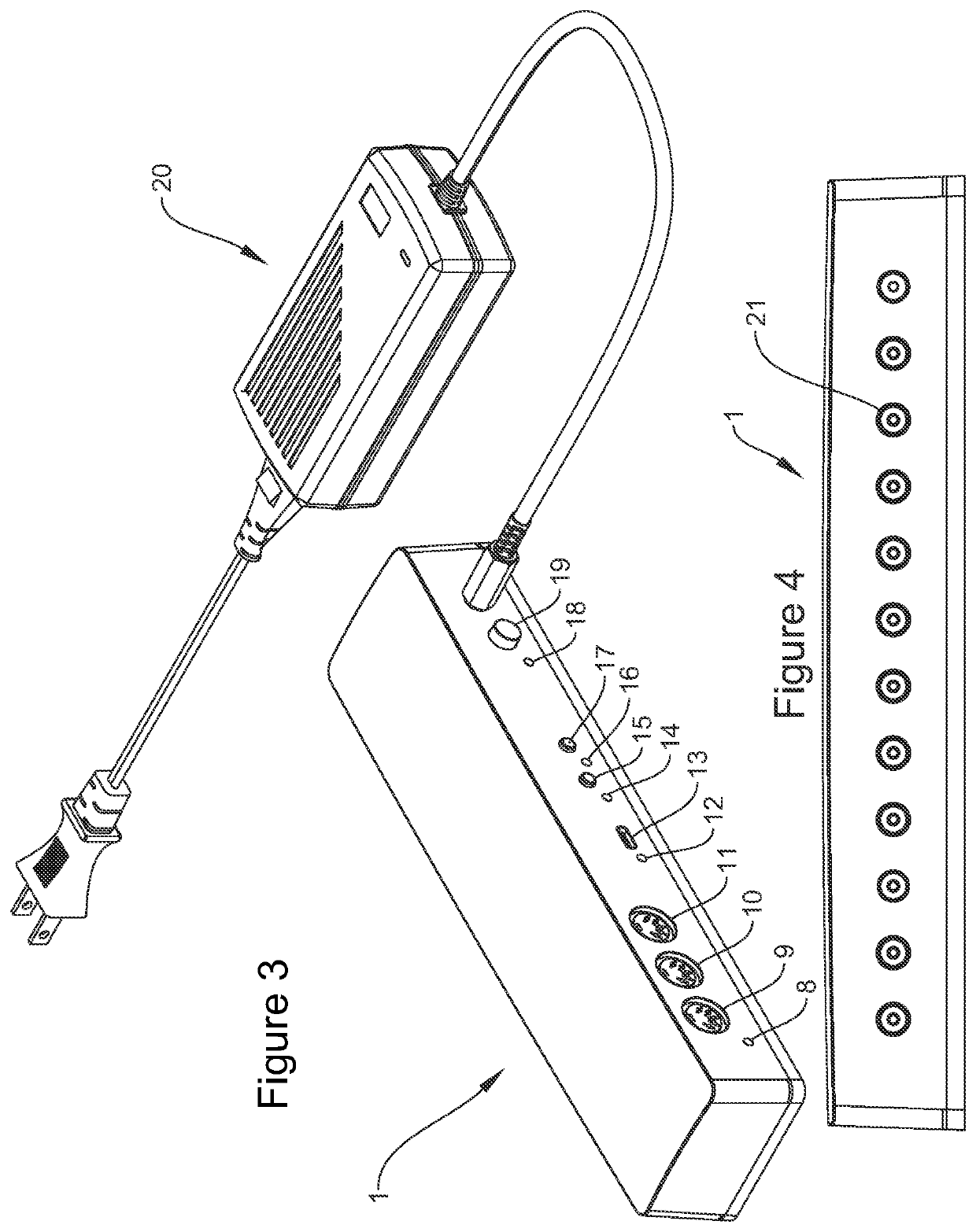
[0036]FIG. 1 is a perspective view of one preferred embodiment of the present invention, shown apart from the drums or mounting accessories with which it is intended for use. Therein is one preferred embodiment of the MIDI decoder 1 and a plurality of the preferred embodiment of the actuators 2. The operating procedures of the MIDI decoder 1 are generally described by the flow chart representation of FIG. 17. Further illustrated are four examples of suitable percussion implements, namely a small, rigid mallet head 3, a brush 4, a drumstick 5, and a felt mallet 6. The percussion implements 3-6 shown are examples only and demonstrate the flexibility and customizability of the system. Any number and combination of percussion implements can be selected and attached to the actuators by means further described hereinafter.

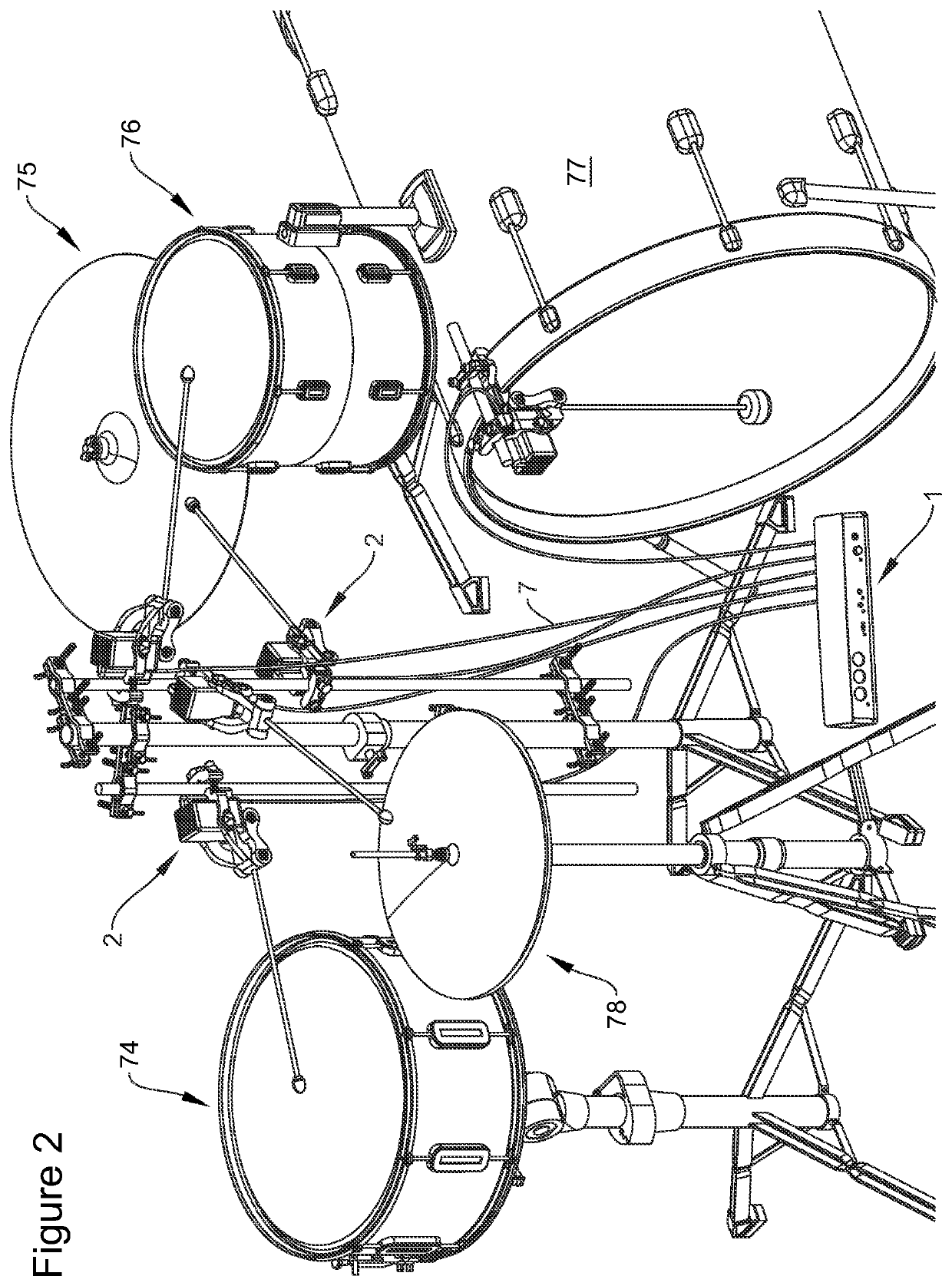
[0037]FIG. 2 illustrates the preferred embodiment of the MIDI decoder 1 and a plurality of actuators 2, assembled to a typical drum set, using hardware and accessories, ...


PUM


Abstract

A system and method for automatic drumming. A MIDI decoder (1) receives MIDI serial data in real-time, decodes said MIDI serial data to obtain playing instructions, and signals at least one actuator (2) to strike at least one drum according to said decoded playing instructions. User inputs for selecting the MIDI channel and assigning MIDI notes to drums may be provided. The intensity of percussion may be controlled by the MIDI velocity and may be overridden by the user at the MIDI decoder. The at least one actuator may employ a solenoid and comprises features to mitigate latency between the MIDI serial data received and the drum hit. The at least one actuator may comprise a clamping or securement means enabling fast and convenient repositioning thereof. The at least one actuator may comprise means for substitution of a percussion implement, such as a drumstick, brush, or mallet.

Description

BACKGROUND OF THE INVENTION[0001]The present invention relates generally to the field of automatic percussion musical instruments. Specifically, the present invention relates to systems and methods for automatic drumming.[0002]Heretofore, various inventions have been provided for automatically performing drums. The known automatic drumming systems typically comprise a controller that signals one or more drum-striking actuators. The known controllers typically comprise means for music data storage or means for connecting to a music data storage medium. Music data is generally instructions for performing music, including notes, intensity, timing, etc. The term intensity is consistent with the terms loudness, dynamic level, and volume. The music data performed by the known automatic drumming systems is typically composed prior to a performance and saved to a data storage medium. Furthermore, the music data is frequently arranged and modified to correct for actuator latency, the time de...

Claims


Application Information

Patent Timeline
IPC IPC(8): G10D13/10G10D13/12G10F1/08G10H1/00G10F5/02
CPCG10D13/26G10D13/12G10F1/08G10F5/02G10H1/0008G10H1/0066G10H2230/281G10H2240/285G10H1/42
Inventor BURNS, JR., MICHAEL BRYAN
Owner BURNS JR MICHAEL BRYAN
Learn More