

Actuator, valve actuator unit and valve
a technology for actuators and actuator bodies, applied in the direction of diaphragm valves, operating means/release devices of valves, engine diaphragms, etc., can solve the problems of long adhesive force, low effect of protective layer on mechanical properties of actuator bodies, and thin layer only having very minor effects on actuator operation characteristics
- Summary
- Abstract
- Description
- Claims
- Application Information
AI Technical Summary
Benefits of technology
Problems solved by technology
Method used
Image

Examples
first embodiment
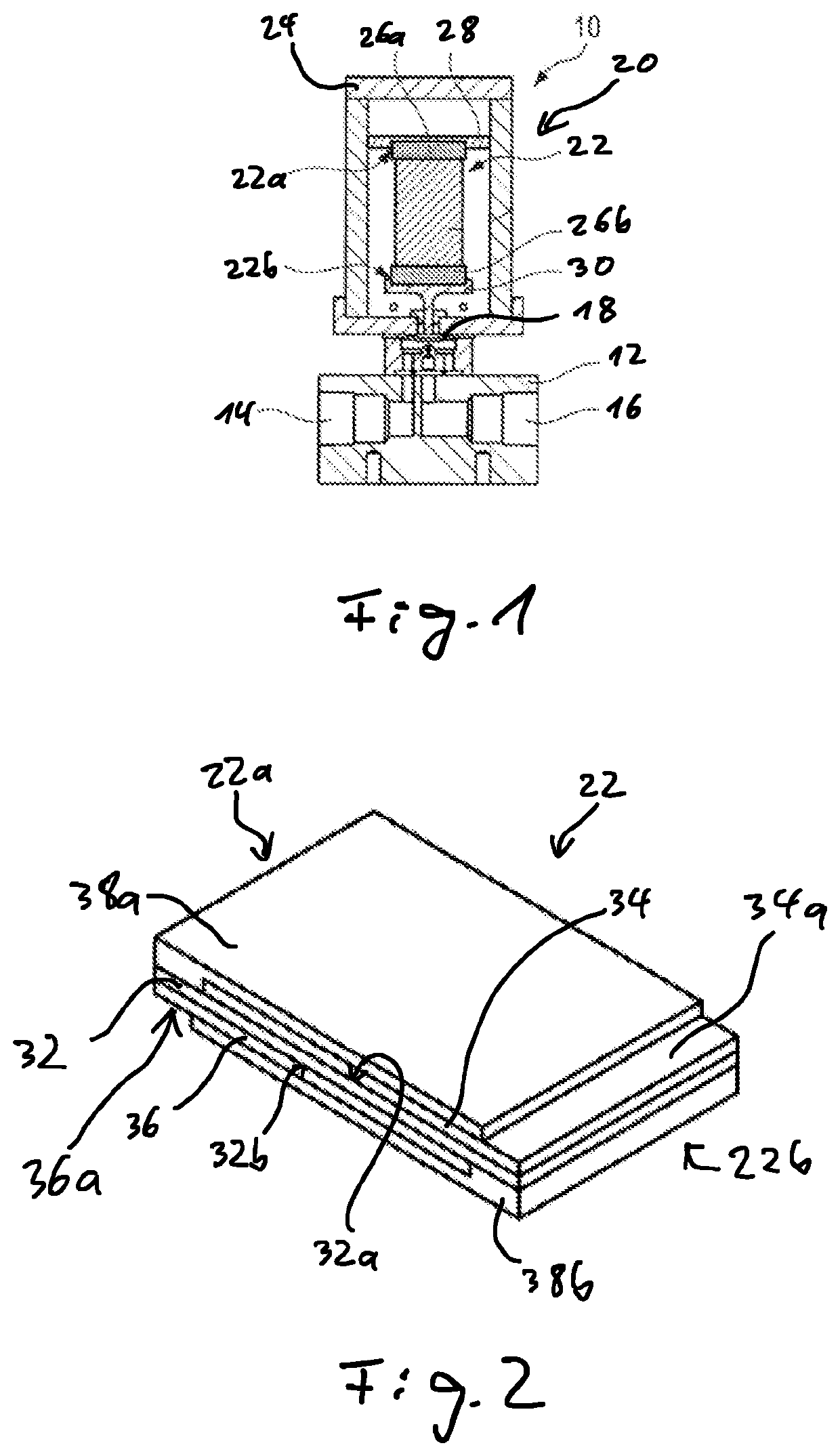
[0046]The valve actuator unit 20 comprises an actuator 22 which is a valve actuator.
[0047]The actuator 22 is arranged in a housing 24.
[0048]The housing 24 is generally filled with ambient air, i.e. all portions of the housing 24 which are not occupied by the actuator 22 or other elements of the valve actuator unit 20 are occupied by ambient air.
[0049]A first end 22a of the actuator 22 is mounted on the housing 24 via a first mounting interface 26a and a holding bar 28.
[0050]A second end 22b of the actuator 22 which is opposed to the first end 22a thereof is operatively coupled to the valve element 18 via a second mounting interface 26b and a coupling member 30.
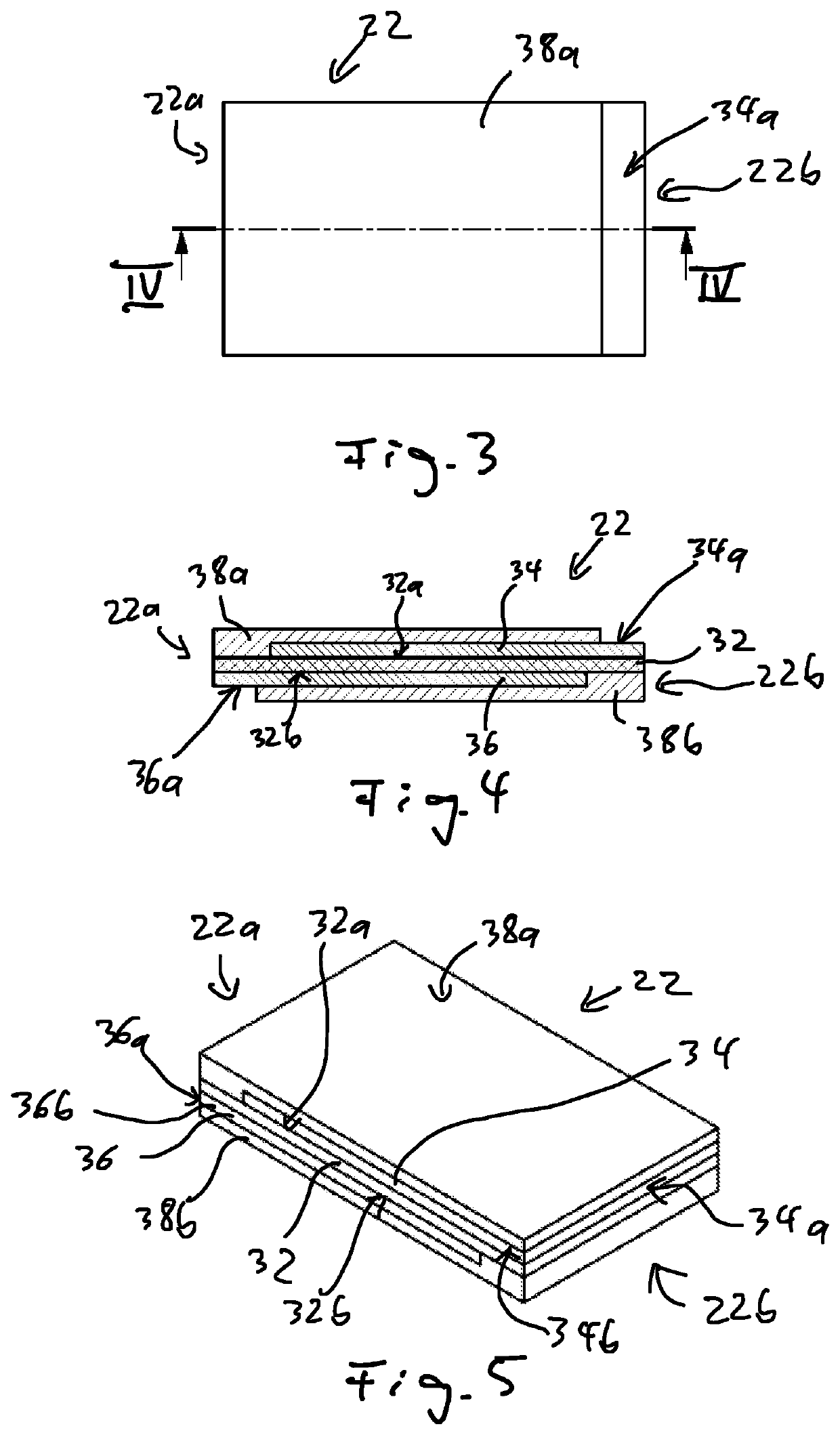
[0051]FIGS. 2 to 4 show the actuator 22 in more detail.
[0052]The actuator 22 comprises an actuator body 32 which is made of a dielectric elastomeric material.
[0053]In the example shown the actuator body 32 has the form of a strip. It comprises an upper surface 32a and a lower surface 32b.
[0054]A first electrode 34 is attache...
second embodiment
[0069]FIGS. 5 to 7 show the actuator 22.
[0070]The actuator 22 according to the second embodiment is suitable for replacing the actuator 22 according to the first embodiment in the valve actuator unit 20 of the valve 10 as shown in FIG. 1.
[0071]In the following, only the differences between the actuator 22 of the first embodiment and the second embodiment will be explained.
[0072]In the second embodiment, the protective layers 38a, 38b fully cover the sides of the actuator 22 corresponding to the upper surface 32a and the lower surface32b of the actuator body 32.
[0073]For this reason, the connection surfaces 34a, 36a are provided on the end faces of the corresponding electrodes 34, 36 facing the respective end 22a, 22b of the actuator (see especially FIGS. 5 and 7).
[0074]In an alternative, the connection surface 34b, 36b are arranged on lateral side faces of the corresponding electrodes (see FIG. 5).
[0075]The actuator 22 according to the first and second embodiments is a single-layer ...
third embodiment
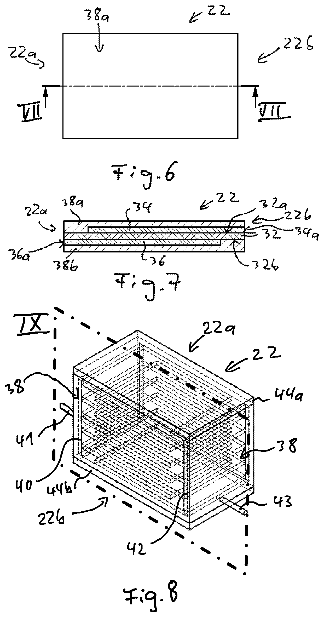
[0076]FIGS. 8 and 9 show an actuator 22 which is a multi-layer actuator or stack actuator.
[0077]The actuator 22 according to the third embodiment is also suitable for replacing the actuator 22 according to the first embodiment in the valve actuator unit 20 of the valve 10 as shown in FIG. 1.
[0078]In the following, the actuator 22 according to the third embodiment will be explained by only referring to the differences with respect to the first and second embodiments.
[0079]The exemplary actuator 22 comprises a total of five electrodes 36 being electrically connected to a first connection means 40 being substantially plate-shaped.
[0080]The first connection means 40 is electrically connected to a wire 41 which can be connected to a voltage source.
[0081]Moreover, a total of five electrodes 34 is provided. These electrodes are electrically connected to a second connection means 42 which is also substantially plate-shaped.
[0082]The second connection means 42 is electrically connected to a...
PUM
 Abstract
Description
Claims
Application Information