Signal generation device

a signal generation and signal technology, applied in the direction of code conversion, electrical equipment, frequency-division multiplex details, etc., can solve the problem of increasing the capacity of the communication system, and achieve the effect of high-precision compensation

Active Publication Date: 2022-09-06
NIPPON TELEGRAPH & TELEPHONE CORP
View PDF8 Cites 0 Cited by
  • Summary
  • Abstract
  • Description
  • Claims
  • Application Information

AI Technical Summary

Benefits of technology

[0029]As described above, according to the present invention, a high-quality signal can be generated through highly precise compensation with a computational load smaller than those in conventional technologies, in a signal generating device that can generate a signal of a bandwidth broader than an output bandwidth of a single sub DAC by using a plurality of sub DACs and a high-speed analog device.

Problems solved by technology

However, the DAC manufactured using a current CMOS platform has an analog output bandwidth of about 20 GHz, which is insufficient and causes one of bottlenecks in realizing an increase in the capacity of a communication system.

Method used


Image

  • Signal generation device
  • Signal generation device
  • Signal generation device

Examples


first embodiment

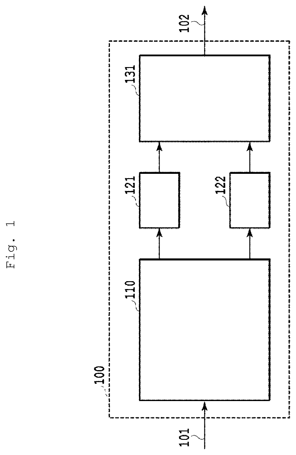
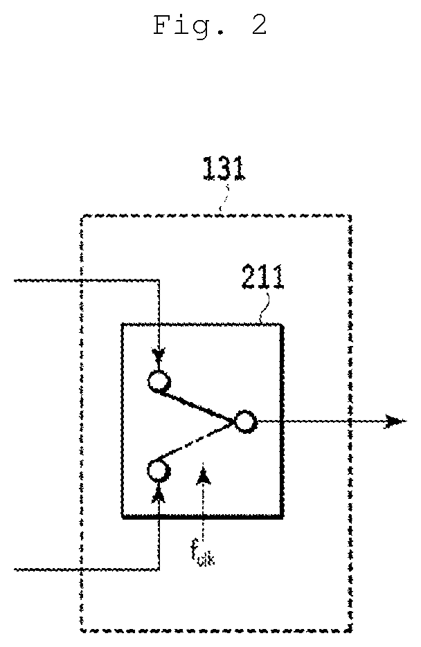
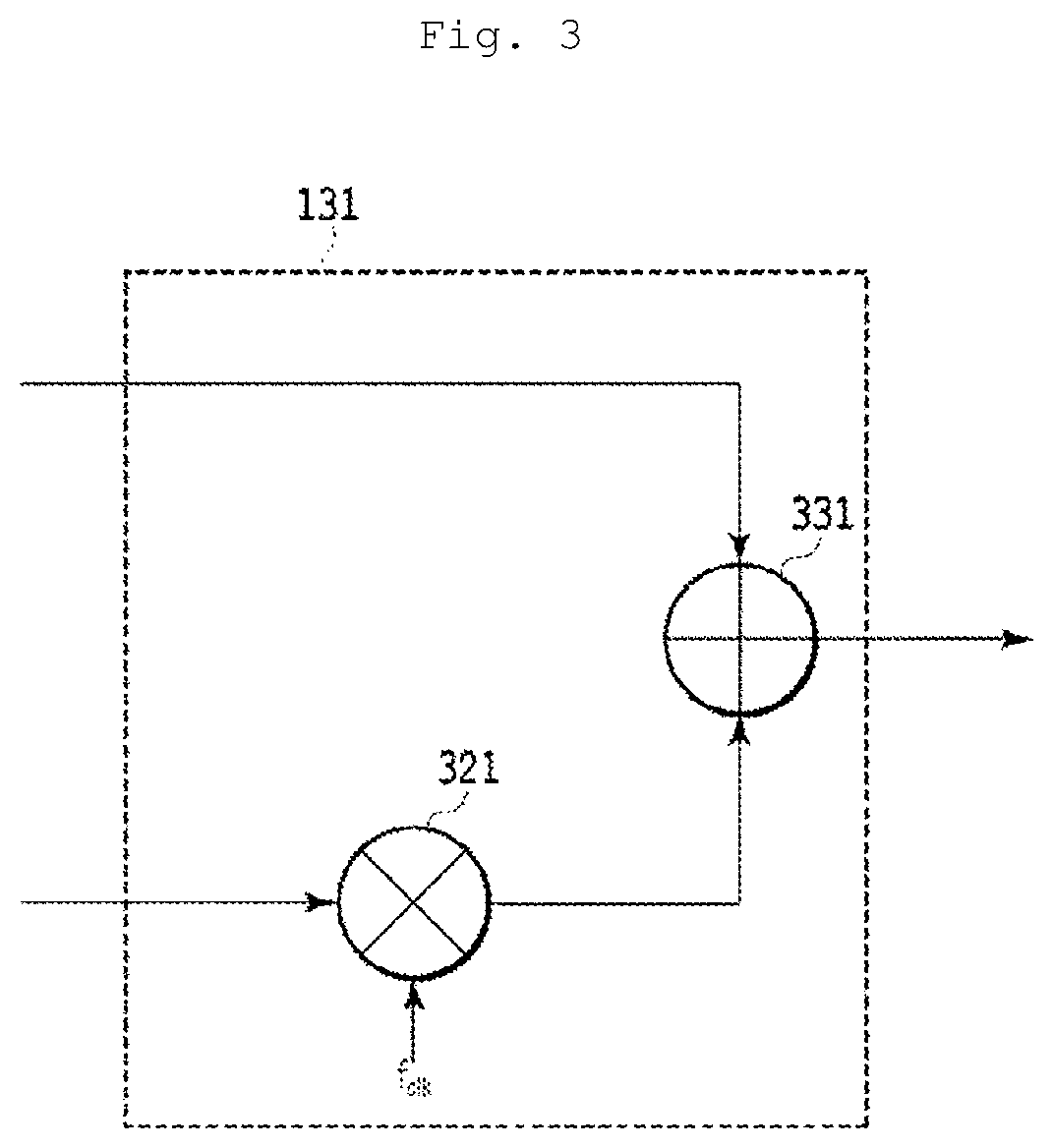
[0057]FIG. 1 is a diagram schematically showing a configuration of a signal generating device according to a first embodiment of the present invention. A signal generating device 100 is constituted by a digital signal processing unit 110 to which an input signal 101 is input, sub DACs 121 and 122, and a broadband analog signal generating unit 131 that outputs an output signal 102. When the number of sub DACs is represented by M (M is an integer equal to or greater than 2), M=2 in this example, but the operation principle can also be extended to a configuration in which M≥3.

[0058]Assume that the analog bandwidth of the sub DACs 121 and 122 is fB. The broadband analog signal generating unit 131 has a function of outputting a broadband signal having a frequency range from 0 to about 2fB as the output signal 102 by generating images by shifting the frequency of each of signals input from the sub DACs 121 and 122 by an integral multiple of fB and superimposing the images.

[0059]Examples o...

second embodiment

[0133]FIG. 10 is a diagram schematically showing a configuration of a signal generating device according to a second embodiment of the present invention. A signal generating device 900 is constituted by a digital signal processing unit 910 to which an input signal 901 is input, sub DACs 921 to 923, and a broadband analog signal generating unit 931 that outputs an output signal 902. When the number of sub DACs is represented by M (M is an integer equal to or greater than 2), M=3 in this example.

[0134]Assume that the analog bandwidth of the sub DACs 921 to 923 is fB. The broadband analog signal generating unit 931 has a function of outputting a broadband signal in a frequency range from 0 to about 3fB as the output signal 902 by generating images by shifting the frequency of each of signals input from the sub DACs 921 to 923 by an integral multiple of fB and superimposing the images.

[0135]Examples of specific configurations of the broadband analog signal generating unit 931 that can b...

third embodiment

[0172]FIG. 16 is a diagram schematically showing a configuration of a signal generating device according to a third embodiment of the present invention. A signal generating device 1400 is constituted by a digital signal processing unit 1410 to which an input signal 1401 is input, sub DACs 1421 to 1424, and a broadband analog signal generating unit 1431 that outputs an output signal 1402. When the number of sub DACs is represented by M (M is an integer equal to or greater than 2), M=4 in this example.

[0173]Assume that the analog bandwidth of the sub DACs 1421 to 1424 is fB. The broadband analog signal generating unit 1431 has a function of outputting a broadband signal in a frequency range from 0 to about 4fB as the output signal 1402 by generating images by shifting the frequency of each of signals input from the sub DACs 1421 to 1424 by an integral multiple of fB and superimposing the images.

[0174]Examples of specific configurations of the broadband analog signal generating unit 14...


PUM


Abstract

A signal generating device includes a digital signal processing unit, M sub DACs of which an analog bandwidth is fB, M being an integer equal to or greater than 2, a broadband analog signal generating unit configured to generate a broadband analog signal that includes a component of a frequency of (M-1)fB or more by using M analog signals output from the M sub DACs. The digital signal processing unit includes components for generating M original divided signals that correspond to signals obtained by dividing a desired output signal into M portions on a frequency axis and down-converting the portions to the baseband, components for generating M folded divided signals by folding back the M original divided signals on the frequency axis, and a 2M×M filter that takes the original divided signals and the folded divided signals as inputs and outputs M composite signals to be transmitted to the M sub DACs. The 2M×M filter can set a response function independently for each of 2M2 combinations of input and output.

Description

TECHNICAL FIELD[0001]The present invention relates to a signal generating device that is used for a high-speed signal transmission system, for example, and in which a digital-analog converter is used.BACKGROUND ART[0002]As represented by widespread use of smartphones, the internet traffic continues to increase day by day, and an increase in the capacities of optical fiber communications, wireless communications, line telecommunications, and the like as well as their advanced functionalities are required. As an elemental technology for realizing increased capacities and advanced functionalities of systems, development of efficient network configurations, advanced digital modulation and demodulation systems, optical and electronic devices operable at a high speed, and the like are currently underway. For instance, focusing on a transmission side circuit of a communication device, studies are actively undertaken to perform processing such as advanced multi-level modulation and waveform...

Claims


Application Information

Patent Timeline
Patent Type & Authority Patents(United States)
IPC IPC(8): H04J1/08
CPCH04J1/08H04B1/04H03M1/662
Inventor YAMAZAKI, HIROSHINAGATANI, MUNEHIKONOSAKA, HIDEYUKINAKAMURA, MASANORIMIYAMOTO, YUTAKA
Owner NIPPON TELEGRAPH & TELEPHONE CORP
Why Eureka
Try Eureka