
Impregnated veils

a technology of impregnated veils and veils, which is applied in the field of veils, can solve the problems of carbon fiber post-mold reworking, high cost of surface preparation and rework, and add to the cost prohibitive nature of automotive molded parts, so as to reduce fiber splitting and improve visual quality.

Active Publication Date: 2022-09-13
MAGNA EXTERIORS INC
View PDF21 Cites 0 Cited by
  • Summary
  • Abstract
  • Description
  • Claims
  • Application Information

AI Technical Summary

Benefits of technology

The use of impregnated veils in the compression molding process leads to improved surface quality, reduced surface defects, and lower production costs by minimizing fiber movement and resin starvation, resulting in parts that are ready for painting with minimal rework, suitable for both decorative and structural applications.

Problems solved by technology

Traditionally, carbon fiber composites have known surface issues for fiber lines and resin rich domains on the surface causing post-mold reworking of parts to meet appearance and quality standards.
However, currently, composite suppliers supply dry and impregnated veils, but not assembled in the inventive fashion of this subject application or used for the new manufacturing process for carbon fiber continuous pre-impregnated materials, as set forth in this present application.
One common problem is being able to provide out-of-the-mold Class “A” surfaces ready for paint (all carbon processes require surface preparation work to make them ready for Class A).
Surface and preparation and rework of carbon fiber is expensive and adds to the cost prohibitive nature of articles molded in this material for automotive.
In addition, material, part geometry, and the process can create additional defects in the subject unique compression molding process.
Some systems also include dry veils, which have significant disadvantages such as not being acceptable for three dimensional parts (3D), etc.
However, if the integrity of the pre-preg is weak then splits will develop when the clamp force is applied.
In general, the worse the pre-preg quality, the worse the resin rich domain and resulting read through—especially in areas with more complex geometries.
Another problem is that when heat is applied during compression, fiber washout results and splits will separate even further.
Poor fiber interlacing can result in splits or otherwise compromise pre-preg integrity.

Method used


Image

  • Impregnated veils
  • Impregnated veils
  • Impregnated veils

Examples


Embodiment Construction

[0016]The following description of the preferred embodiment(s) is merely exemplary in nature and is in no way intended to limit the invention, its application, or uses.

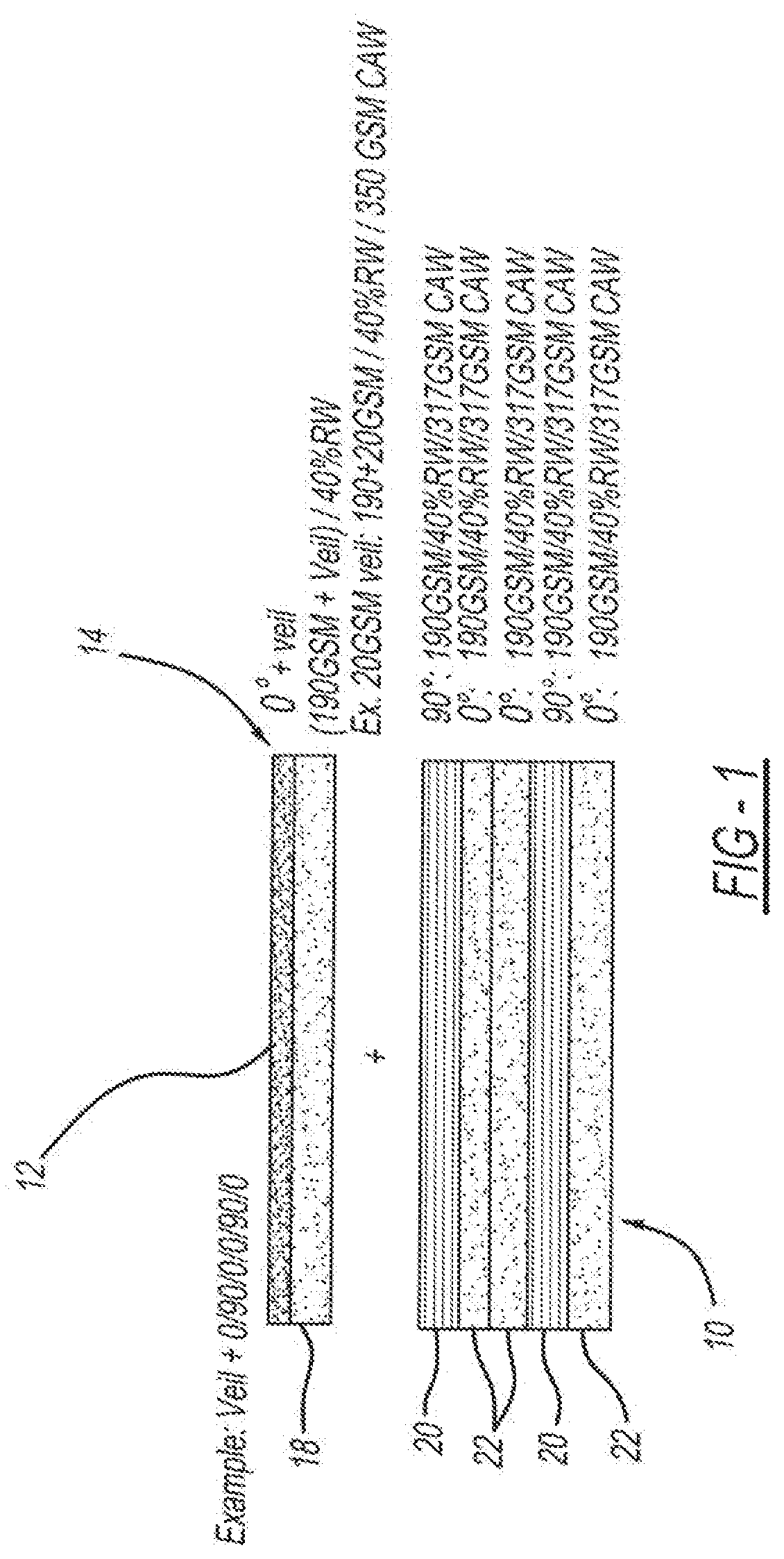
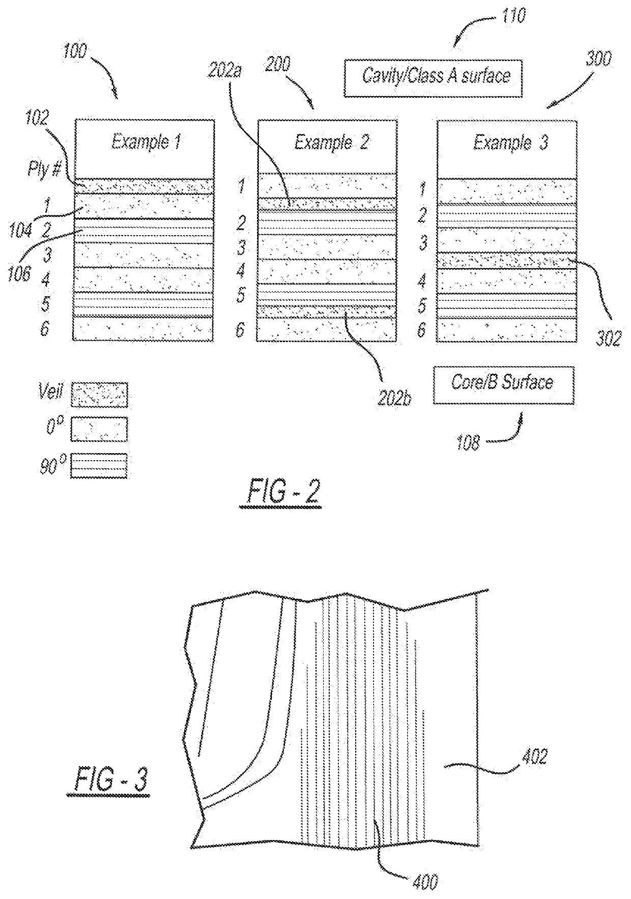
[0017]Referring to the Figures generally, the present invention is directed to veils incorporated into pre-impregnated carbon fiber for compression molding processing. At least one veil is positional in any predetermined location of the ply stack layup configuration suitable for providing the desired surface quality and any other desired predetermined properties.

[0018]In general, impregnated veils for use in compression molding processing of pre-impregnated carbon fiber pre-impregnated continuous and / or discontinuous thermoset and thermoplastic materials is provided, according to the present invention. These veils are incorporated within the process, e.g., most preferably in the filming or laminating stages, of the pre-pregging (either hotmelt or solvent based processes) in a resin chosen from variety of resins, e.g.,...


PUM

PropertyMeasurementUnit
temperatureaaaaaaaaaa
clamp forceaaaaaaaaaa
thicknessaaaaaaaaaa

Abstract

Impregnated veil and compression molding process of reinforcing fiber pre-impregnated continuous and discontinuous thermoset and thermoplastic materials. Veils are incorporated within the process, filming or laminating stages of the pre-pregging, either hotmelt or solvent based processes, in a variety of chosen resins. The veils help to improve visual part quality, reduce fiber splitting, and provide an isolating material in applications where incompatible materials must exist.

Description

CROSS-REFERENCE TO RELATED APPLICATIONS[0001]This application is a National Stage of PCT International Application No. PCT / IB2016 / 057632filed Jun. 14, 2017 which claims the benefit of U.S. Provisional Patent Application No. 62 / 266,987, filed Dec. 14, 2015. The disclosures of the above applications are incorporated herein by reference.FIELD OF THE INVENTION[0002]The present invention relates to veil layer(s) incorporated in pre-impregnated materials for compression molding in the manufacture of parts such as automotive parts.BACKGROUND OF THE INVENTION[0003]Molding of various plastic materials is a common method used to create parts for various applications. Traditionally, carbon fiber composites have known surface issues for fiber lines and resin rich domains on the surface causing post-mold reworking of parts to meet appearance and quality standards. Defects include visible fiber read through on painted surfaces, especially with resin rich domains on the surface. At higher temperat...

Claims


Application Information

Patent Timeline
Patent Type & Authority Patents(United States)
IPC IPC(8): B29C70/34C08J5/04C08J5/24B29C70/08B29K33/00B29K67/00B29K707/04B29K709/08
CPCB29C70/34B29C70/08C08J5/042C08J5/043C08J5/046C08J5/24B29K2033/08B29K2067/00B29K2707/04B29K2709/08C08J2333/08C08J2367/00B29C70/345C08J5/243
Inventor INGRAM, JOHN A.CALDER, DAVID A.MCNULTY, DANIEL P.TRUDEAU, PAUL A.MOORE, HENRY E.
Owner MAGNA EXTERIORS INC
Learn More