Elevator pit ladder apparatus
a ladder and ladder technology, applied in the field of ladders, can solve the problems of occupying workers' time and effort in moving ladders from a retracted position to a use position
- Summary
- Abstract
- Description
- Claims
- Application Information
AI Technical Summary
Benefits of technology
Problems solved by technology
Method used
Image

Examples
embodiment 1
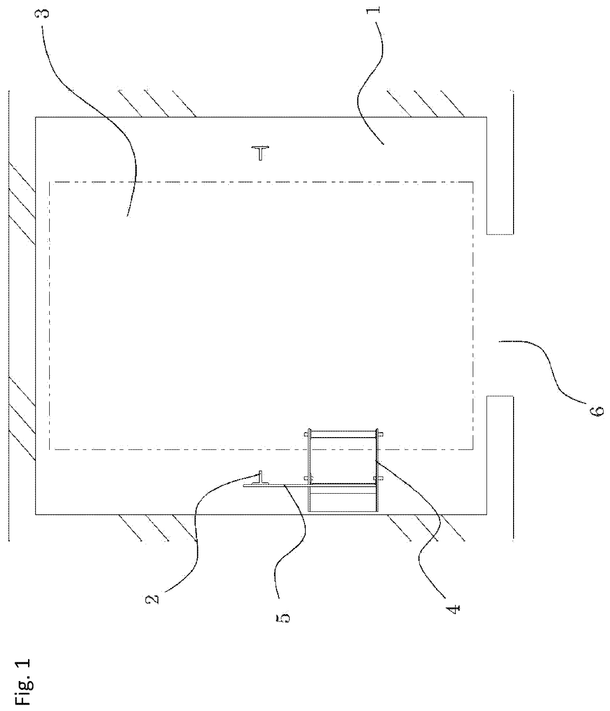
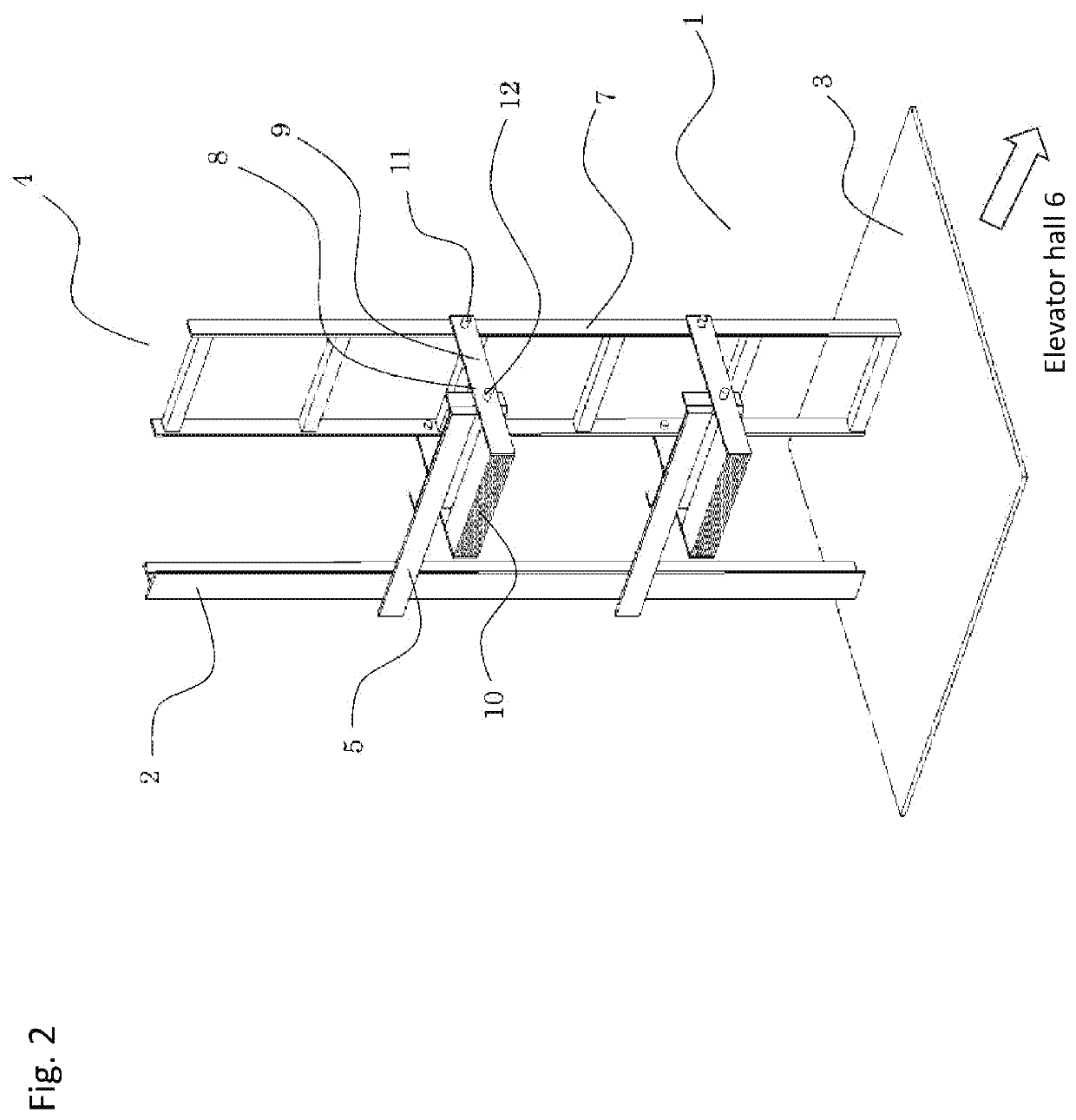
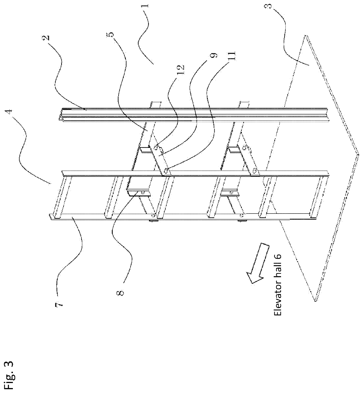
[0016]FIGS. 1 to 6 illustrate an elevator pit ladder apparatus according to Embodiment 1 of the present invention. FIG. 1 is a plan view showing the entire pit ladder apparatus in use. FIG. 2 is a perspective view showing the pit ladder apparatus of FIG. 1. FIG. 3 is a perspective view showing the pit ladder apparatus of FIG. 2, seen from a different direction. FIG. 4 is a plan view showing the entire pit ladder apparatus in its retracted state. FIG. 5 is a perspective view showing the pit ladder apparatus of FIG. 4. FIG. 6 is a perspective view showing the pit ladder apparatus of FIG. 5, seen from a different direction.
[0017]In the figures, in an elevator hoistway 1, a guide rail 2 is standing vertically to guide an elevator car. In a pit area 3 inside the hoistway 1, a pit ladder apparatus 4 is fixed to the guide rail 2 via a fixing metal frame 5. The pit ladder apparatus 4 is disposed at a position where the pit ladder apparatus 4 does not interfere with operation of the elevator...
embodiment 2
[0027]FIG. 7 is a perspective view to illustrate a main part of a pit ladder apparatus 13 according to Embodiment 2 of the present invention. According to Embodiment 2 of the present invention, the difference from Embodiment 1 is that a counter weight 14 of the pit ladder apparatus 13 is made up of stacked weights. The same or equivalent components other than the difference are given the same symbols and their description will be omitted.
[0028]As shown in the figure, the counter weight 14 is made up of stacked weights. The minimum unit of the weights corresponds to a single weight that is formed to be a flat plate. Flat plates having the same shape as the flat plate described above are disposed and the number is selectable and either one or plural.
[0029]Next, operation of the pit ladder apparatus 13 according to Embodiment 2 will be described. Referring to the figure, the weights of the ladder 7 and the counter weight 14 in a position change unit 15 as well as the distances from the...
embodiment 3
[0031]FIG. 2 and FIG. 3 illustrate a pit ladder apparatus 4 according to Embodiment 3 of the present invention. The pit ladder apparatus 4 according to Embodiment 3 of the present invention is different from the previous embodiments in that a lower end of the ladder 7 at the use position is in contact with a pit floor of the pit area 3. The same or equivalent components other than the difference are given the same symbols and their description will be omitted.
[0032]As shown in the figures, the lower end of the ladder 7 at the use position is disposed to be in contact with the pit floor of the pit area 3. Next, operation of the pit ladder apparatus 4 according to Embodiment 3 will be described. Referring to figures, when a worker moves up and down on the ladder 7 at the use position, a load applied as the worker moves up and down is applied from the ladder 7 to the guide rail 2 via the mounting arms 9 and the fixing metal frame 5. At this time, strength is needed for the guide rail 2...
PUM
 Abstract
Description
Claims
Application Information
 - Generate Ideas
- Intellectual Property
- Life Sciences
- Materials
- Tech Scout
- Unparalleled Data Quality
- Higher Quality Content
- 60% Fewer Hallucinations
Browse by: Latest US Patents, China's latest patents, Technical Efficacy Thesaurus, Application Domain, Technology Topic, Popular Technical Reports.
© 2025 PatSnap. All rights reserved.Legal|Privacy policy|Modern Slavery Act Transparency Statement|Sitemap|About US| Contact US: help@patsnap.com