
Solar light concentrating device capable of being stationary for successive days

A solar energy concentration and positioning device technology, applied in the field of solar energy utilization, can solve the problems of increasing the cost of solar thermal utilization systems, difficulty in production and assembly, and increasing production costs, etc.

Active Publication Date: 2017-01-18
王瑞峰
View PDF6 Cites 0 Cited by
  • Summary
  • Abstract
  • Description
  • Claims
  • Application Information

AI Technical Summary

Problems solved by technology

But doing so not only increases the cost of the solar thermal utilization system, but also increases the technical difficulty of production, use and daily maintenance of this device
Although some compound paraboloid technologies do not need automatic tracking devices to cooperate with them, which reduces technical difficulty and production costs, this technology also has some disadvantages: First, the shape of the concentrating surface is relatively complicated, and it is difficult to produce and assemble
Second, the concentration factor is not high
Three, the area of ​​the light-gathering surface used is relatively large, which increases the usage of light-gathering materials and thus increases the production cost
Fourth, the azimuth angle of this device needs to be adjusted regularly, but so far, there is still a lack of a very ideal method for adjusting and fixing the reflective condenser, so that it is easy to adjust and firm to fix

Method used


Image

  • Solar light concentrating device capable of being stationary for successive days
  • Solar light concentrating device capable of being stationary for successive days
  • Solar light concentrating device capable of being stationary for successive days

Examples


Embodiment Construction

[0027] This patent can be applied to both the photothermal field and the photoelectric field. If it is applied to the photothermal field, the light energy utilization components described below refer to heat collectors. If it is applied to the photoelectric field, the light energy described below The utilization part refers to a polygonal (triangular, square, etc.) metal tube with photovoltaic cells attached to its outer surface. For the sake of simplicity, all the drawings in this patent are shown as examples of heat collectors used in the photothermal field. If it is applied to the photovoltaic field, it is only necessary to replace the heat collectors in the figure with polygonal metal with photovoltaic cells on the outer surface. Just do it.

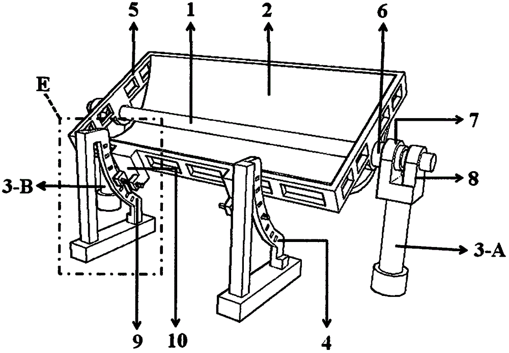
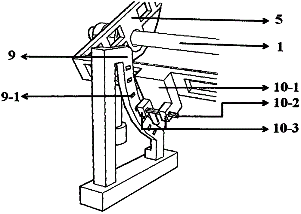
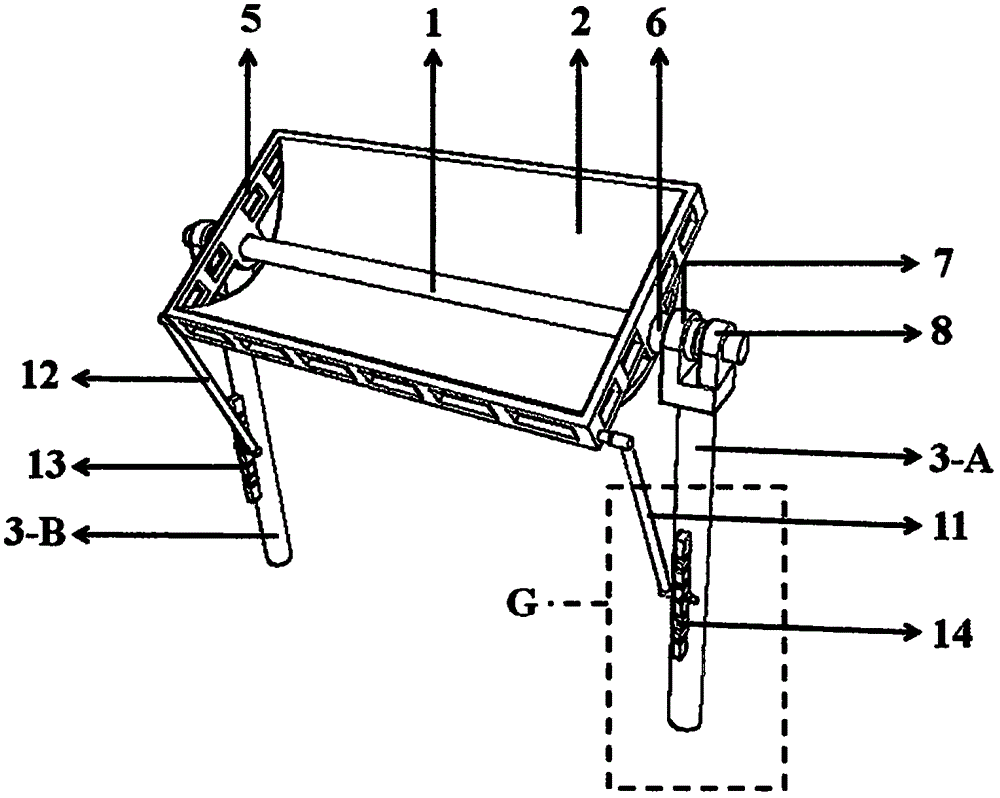
[0028] Below, combine figure 1 The first embodiment of the present invention will be described in detail.

[0029] Fix the two supports (3-A, 3-B in the figure) on a plane, and the light energy utilization component 1 is fixed on t...


PUM


Abstract

The invention provides a solar light concentrating device capable of being stationary for successive days. The solar light concentrating device comprises a reflecting collecting lens, at least two supports, luminous energy utilizing components and a reflecting collecting lens positioning device. The supports are fixed to the same plane and are kept stationary all the year round; the luminous energy utilizing components are fixed to the supports and are also stationary all the year round; the reflecting collecting lens is rotatably connected with the two supports through two rotating shafts, the axes of the two rotating shafts are located on the axes of the corresponding luminous energy utilizing components or near the axes of the corresponding luminous energy utilizing components, and the direction of a main axial surface of the reflecting collecting lens can be changed with the two rotating shafts as the axes by means of external force; and at the interval between two times of adjustment, the reflecting collecting lens is fixed to the reflecting collecting lens positioning device and kept stationary for successive days. The solar light concentrating device is not provided with an automatic tracking device, so that the manufacturing cost of the device is greatly lowered. The solar light concentrating device is kept stationary except for several times to tens of times of manual adjustment in a year, and therefore the device has quite high wind and rain damage resistance. The solar light concentrating device only needs to be adjusted several times to tens of times each year by a user, so that the labor amount of the user is quite small.

Description

technical field [0001] The invention relates to the technical field of solar energy utilization, and more specifically, relates to a solar concentrating device that can be stationary for several consecutive days. Background technique [0002] At present, people pay more and more attention to the development and utilization of solar energy technology, and the role of solar concentrated tracking technology is also increasing. In the field of photovoltaic applications, this technology can greatly save the use of photovoltaic cells; in the field of photothermal applications, this technology can increase the output temperature of solar energy and its heat utilization efficiency. For example: if you do not use concentrating technology, the solar vacuum tube water heater can reach a temperature of 80 or 90 degrees in summer, but only 50 or 60 degrees in winter. This heat production temperature can only meet the needs of daily life. The demand for hot water cannot meet the industri...

Claims


Application Information

Patent Timeline
IPC IPC(8): F24J2/10F24J2/46F24J2/24F24J2/52F24S10/70F24S23/70
CPCF24S23/74F24S25/61F24S25/70F24S25/20F24S30/425H02S40/22H02S20/30F24S2023/872Y02E10/47Y02E10/52
Inventor 王瑞峰
Owner 王瑞峰
Features
  • Generate Ideas
  • Intellectual Property
  • Life Sciences
  • Materials
  • Tech Scout
  • Unparalleled Data Quality
  • Higher Quality Content
  • 60% Fewer Hallucinations
Learn More