Light emitting structure

a technology of light-emitting structure and ring-shaped optical fiber, which is applied in the direction of instrumentation, lighting and heating apparatus, planar/plate-like light guides, etc., can solve the problems of uneven brightness and high price of ring-shaped optical fibers

Active Publication Date: 2022-09-27
PRIMAX ELECTRONICS LTD
View PDF1 Cites 0 Cited by
  • Summary
  • Abstract
  • Description
  • Claims
  • Application Information

AI Technical Summary

Problems solved by technology

In addition, the price of the ring-shaped optical fiber is quite expensive.
If a distance between the light emitting elements and the ring-shaped lens is reduced in order to reduce the occupied space, it may cause uneven brightness.

Method used


Image

  • Light emitting structure
  • Light emitting structure
  • Light emitting structure

Examples


Embodiment Construction

[0028]The advantages and features of the present invention and the method for achieving the same will be described in more detail with reference to exemplary embodiments and the accompanying drawings to make it easier to understand. However, the present invention can be implemented in different forms and should not be construed as being limited to the embodiments set forth herein. On the contrary, for those skilled in the art, the provided embodiments will make this disclosure more thorough, comprehensive and complete to convey the scope of the present invention.

[0029]The spatially relative terms in the text, such as “beneath” and “over”, are used to facilitate the description of the relative relationship between one element or feature and another element or feature in the drawings. The true meaning of the spatially relative terms includes other orientations. For example, when the drawing is flipped up and down by 180 degrees, the relationship between the one element and the other e...


PUM

PropertyMeasurementUnit
widthaaaaaaaaaa
distanceaaaaaaaaaa
brightnessaaaaaaaaaa

Abstract

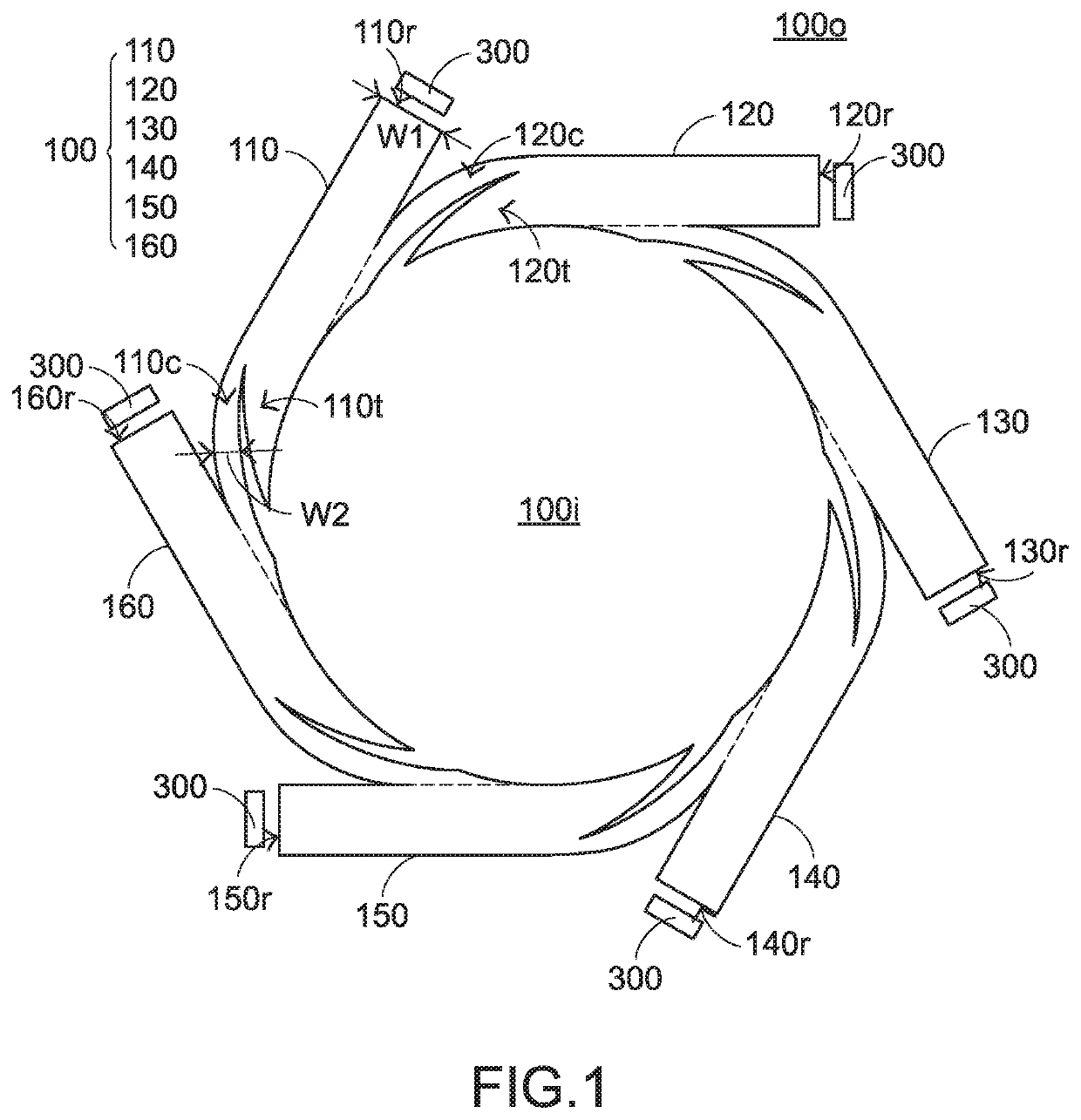
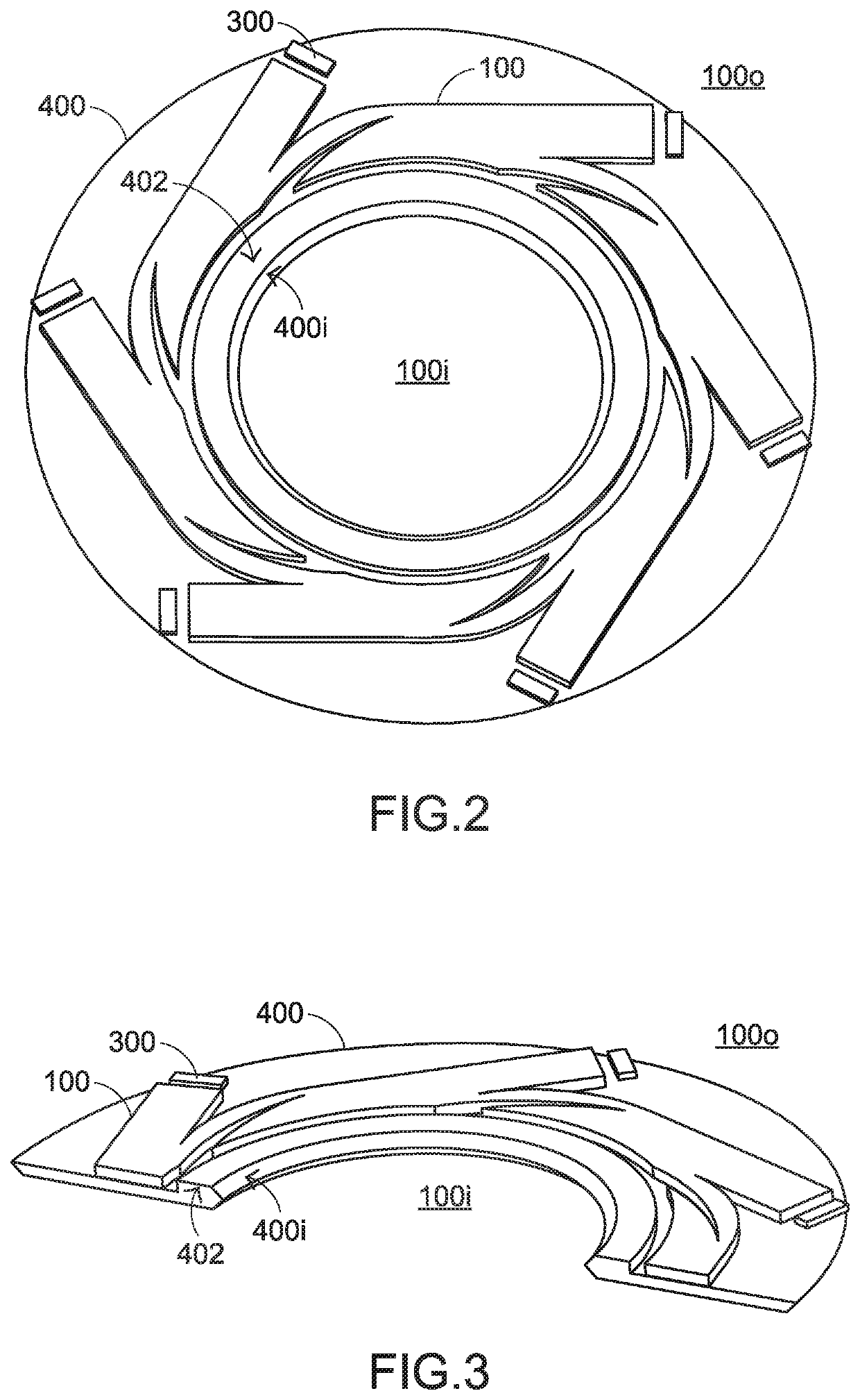
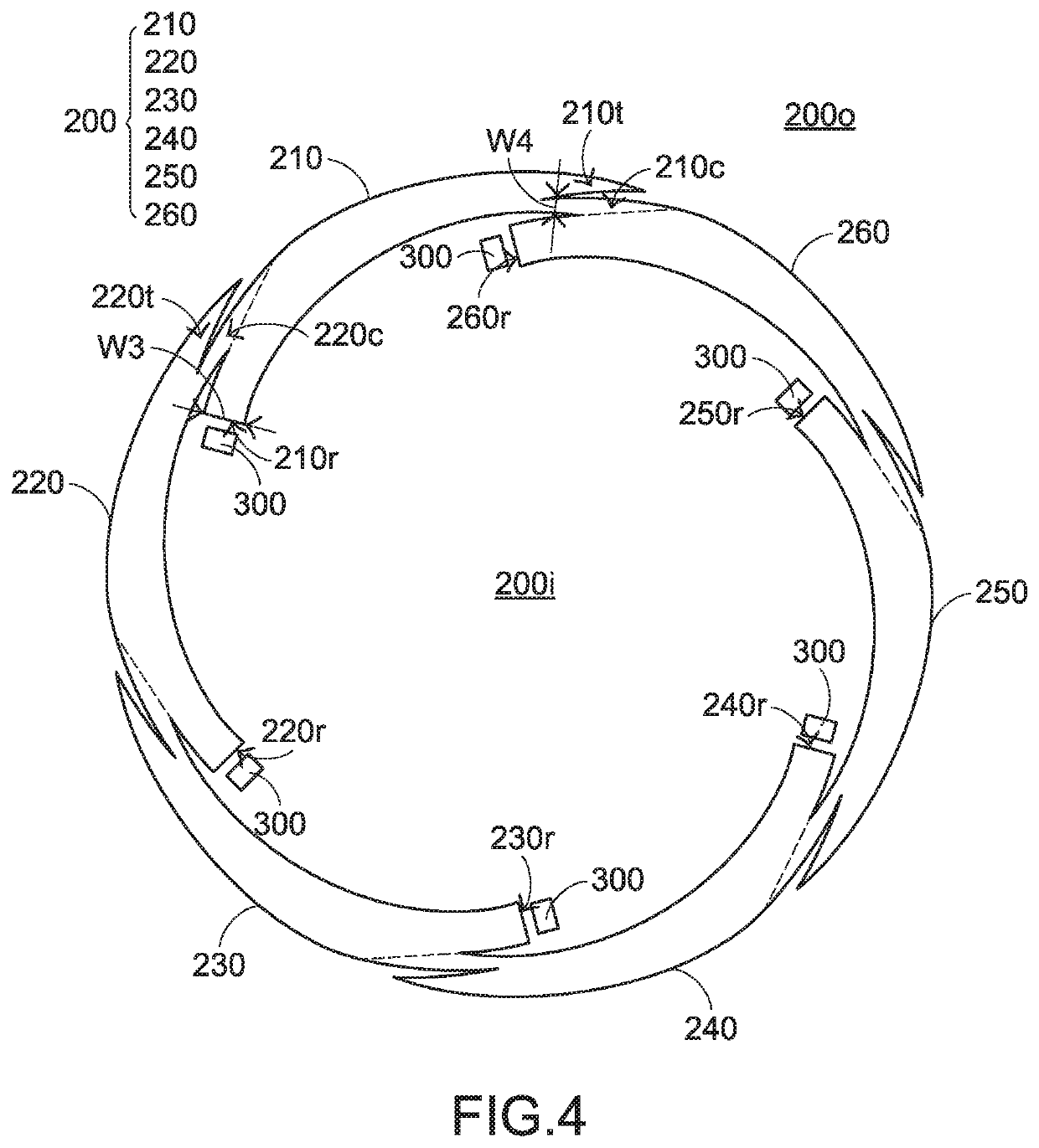
A light emitting structure includes a light guide ring and a plurality of light emitting elements. The light guide ring has a plurality of light guide portions connected in sequence, and each of the light guide portions includes a light source receiving end and a connecting portion opposite to each other, in which one of the light guide portions is connected to another of the light guide portions, and an inner side or an outer side of the one of the light guide portions is connected to the connecting portion of the other of the light guide portions. The light emitting elements are laterally adjacent to the light source receiving ends of the light guide portions, respectively.

Description

FIELD OF THE INVENTION[0001]The present invention relates to a light emitting structure, and particularly relates to a ring-shaped light emitting structure.BACKGROUND OF THE INVENTION[0002]Among the existing ring-shaped light emitting designs, a ring-shaped optical fiber is mainly used, or light emitting elements matched with a ring-shaped lens are used. However, the ring-shaped optical fiber can only emit light in a single region, and a dark region will be formed at a junction of the ring-shaped optical fiber. In addition, the price of the ring-shaped optical fiber is quite expensive. As for the light emitting elements matched with the ring-shaped lens, since the light emitting elements are disposed beneath the ring-shaped lens, those occupy a large space. If a distance between the light emitting elements and the ring-shaped lens is reduced in order to reduce the occupied space, it may cause uneven brightness. Accordingly, there is a need in the art for an improved ring-shaped ligh...

Claims


Application Information

Patent Timeline
Patent Type & Authority Patents(United States)
IPC IPC(8): F21S43/236F21V8/00F21V5/04
CPCG02B6/0045F21V5/045G02B6/0051G02B6/0068G02B6/0078F21V2200/20G02B6/0018G02B6/0028
Inventor CHAN, WEI-PING
Owner PRIMAX ELECTRONICS LTD
Why Eureka
Try Eureka