
Stake implanting tool

a technology of implanting tools and stents, which is applied in the field of agricultural tools, can solve the problems prolonging health problems, and further discomfort for the individual, and achieves the effects of limiting the user's chances of developing any health problems, less time, and limited chan

Active Publication Date: 2022-10-04
EISENHARDT GRANT
View PDF11 Cites 0 Cited by
  • Summary
  • Abstract
  • Description
  • Claims
  • Application Information

AI Technical Summary

Benefits of technology

The present invention provides a stake implanting tool that can be used while standing. This reduces discomfort and health risks associated with manually implanting stakes while kneeling or on hands and knees. The tool also allows for proper placement of stakes without using a hammer, reducing the time and chances of injury. Additionally, a stopping guard prevents the stake from being implanted too deep into the ground, thereby securing the land mat without causing any damage.

Problems solved by technology

Being in such a position can not only cause the individual discomfort, but it also may lead to prolonged health issues.
Moreover, when the land is firm and rigid, having to manually insert the stakes in the ground by hand can lead to further discomfort to the individual.
However, the ability to be in a standing position will limit the user's chances of developing any health issues from having to get into an unfavorable position and having to implant a stake into the ground by hand.
Moreover, the time that it takes a user to place a stake into the slake implanting tool and then implant it into the ground is significantly less than the commonly used methods.
When the stake is too deep into the ground it can damage the land mat and not properly secure the land mat to the ground.
A damaged or ineffective land mat will not help treat the surface from the erosion or any other harm it is experiencing.

Method used


Image

  • Stake implanting tool
  • Stake implanting tool
  • Stake implanting tool

Examples


Embodiment Construction

[0019]Reference is made herein to the attached drawings. Like reference numerals are used throughout the drawings to depict like or similar elements of the stake implanting tool. For the purposes of presenting a brief and clear description of the present invention, the preferred embodiment will be discussed is the stake implanting tool with an elongated body and a slidable handle.

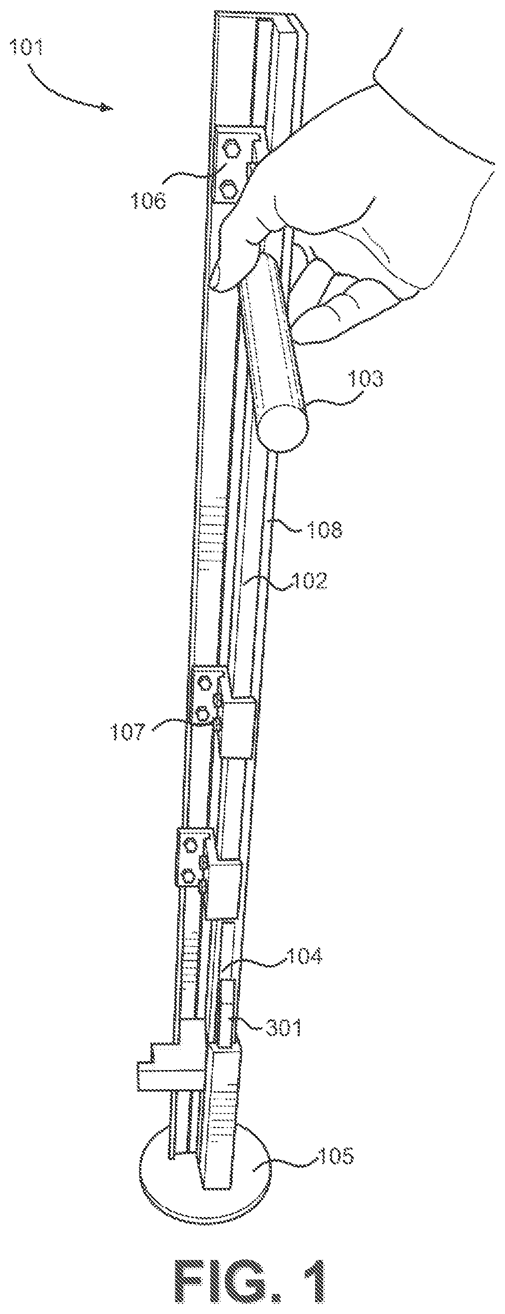
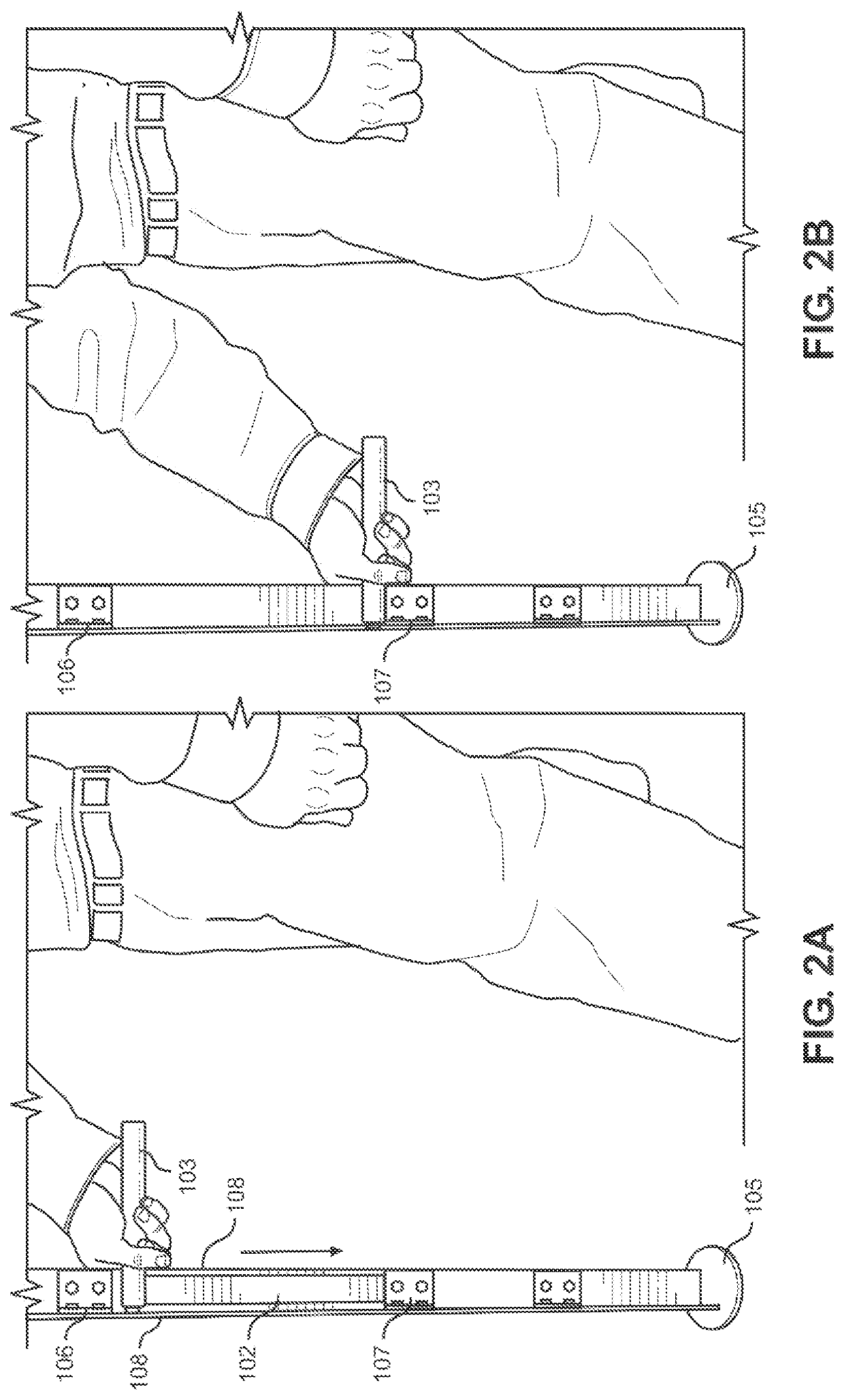
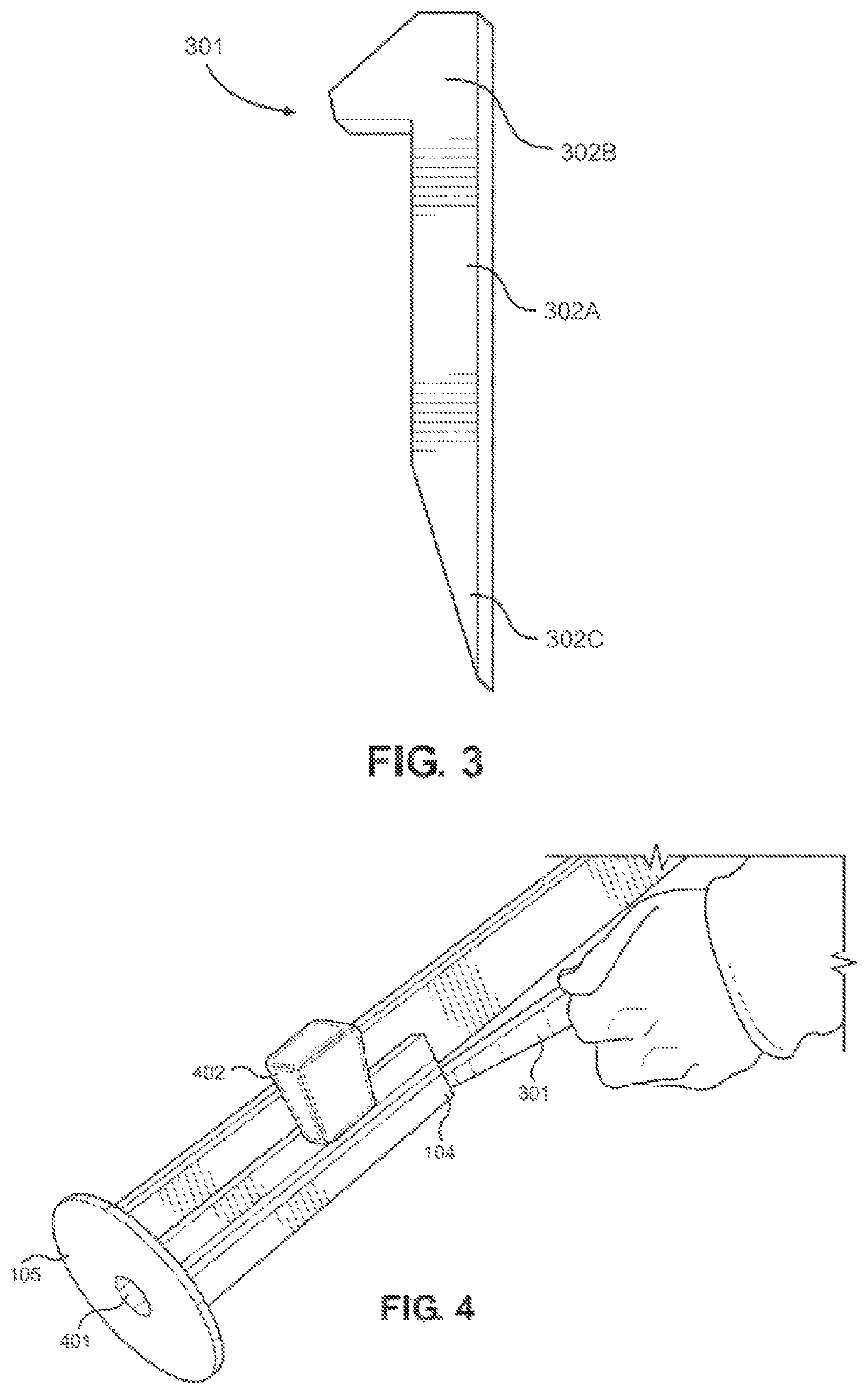
[0020]FIG. 1 shows a perspective view of an embodiment of a stake implanting tool. The stake implanting tool 101 comprises an elongated body, a handle 103, and a rounded base 105. The elongated body is angled. In this embodiment of the stake implanting tool 101, the elongated body is composed from angled aluminum. The angled aluminum makes the stake implanting tool 101 lightweight for the user to carry. The elongated body comprises an upper end and a lower end. The stake implanting tool 101 is designed to allows users to stand in an upright position as they implant stakes into the ground.

[0021]The handle 10...


PUM


Abstract

A stake implanting tool is provided. The stake implanting tool includes an elongated body designed with angled aluminum. The elongated body has a lower end and an upper end. A handle is slidably disposed within a channel defined by the elongated body. A flat stake driver is operably connected to the handle. A slot is disposed on the elongated body. When the handle is in the resting position, a stake is placed within the slot. The stake is retained to the slot by a spring loaded pin. A rounded base disposed on a lower end of the elongated body supports the device on the land mat. An aperture is disposed on the rounded base. In operation, the handle is slid down the channel, the stake is ejected through the aperture into the ground. A stopping guard prevents the stake from being implanted too deep into the ground.

Description

CROSS REFERENCE TO RELATED APPLICATIONS[0001]This application claims the benefit of U.S. Provisional Application No. 62 / 994,394 filed on Mar. 25, 2020. The above identified patent application is herein incorporated by reference in its entirety to provide continuity of disclosure.BACKGROUND OF THE INVENTION[0002]The present invention relates to an agricultural tool. More specifically, the present invention provides a stake implanting tool that has an elongated body with a slidable handle that allows for wooden stakes to be inserted directly into the ground.[0003]After prolonged exposure to wind and water, land surface can start to erode. Land erosion is the process by which material on the surface of the land is dislodged and moved. Eroding land is a dangerous hazard and decreases soil fertility, which can negatively affect the land's ability to grow vegetation. A way to protect against land erosion is to apply an anti-erosion mat to the eroded area. Anti-erosion mats can provide the...

Claims


Application Information

Patent Timeline
Patent Type & Authority Patents(United States)
IPC IPC(8): B25C5/11B25C3/00
CPCB25C5/11B25C3/006A01B79/00E02B3/121E02D17/202
Inventor EISENHARDT, GRANT
Owner EISENHARDT GRANT
Learn More