
Snap trap with set-prevent interference member and rodent orienting side walls

a technology of interference member and snap trap, which is applied in the field of rodent control, can solve the problems of increasing the number of rodent escapes, reducing the interaction of rodents with the trap, and difficult to set chip-clip style snap traps without finger slippag

Active Publication Date: 2022-10-25
WOODSTREAM CORP
View PDF12 Cites 1 Cited by
  • Summary
  • Abstract
  • Description
  • Claims
  • Application Information

AI Technical Summary

Benefits of technology

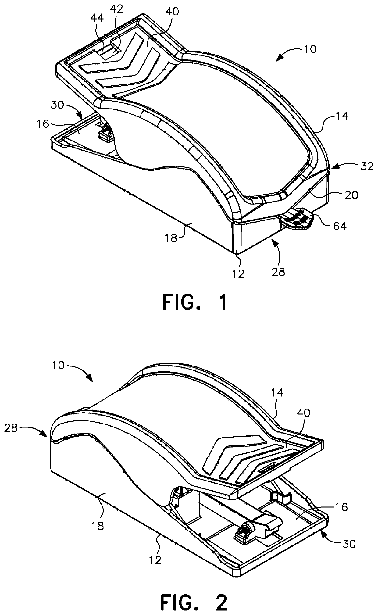
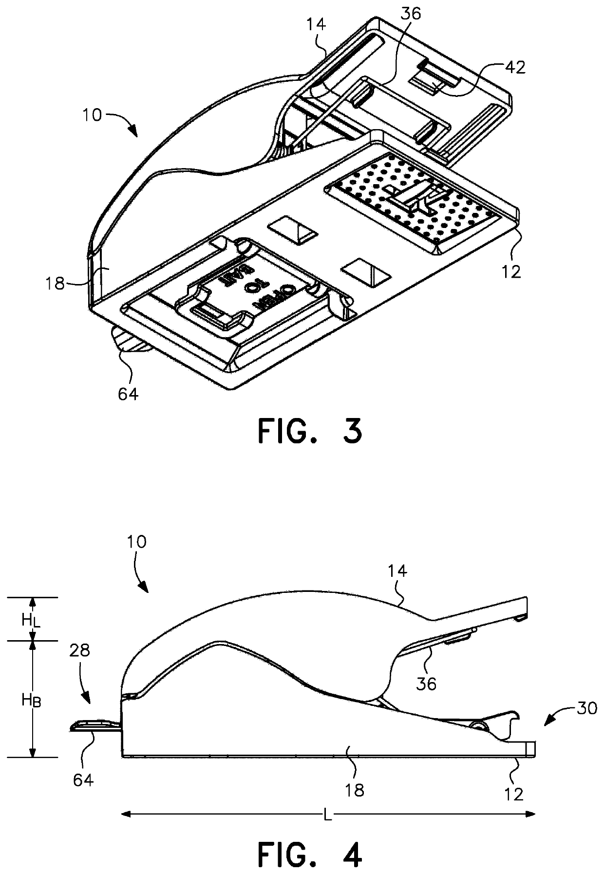
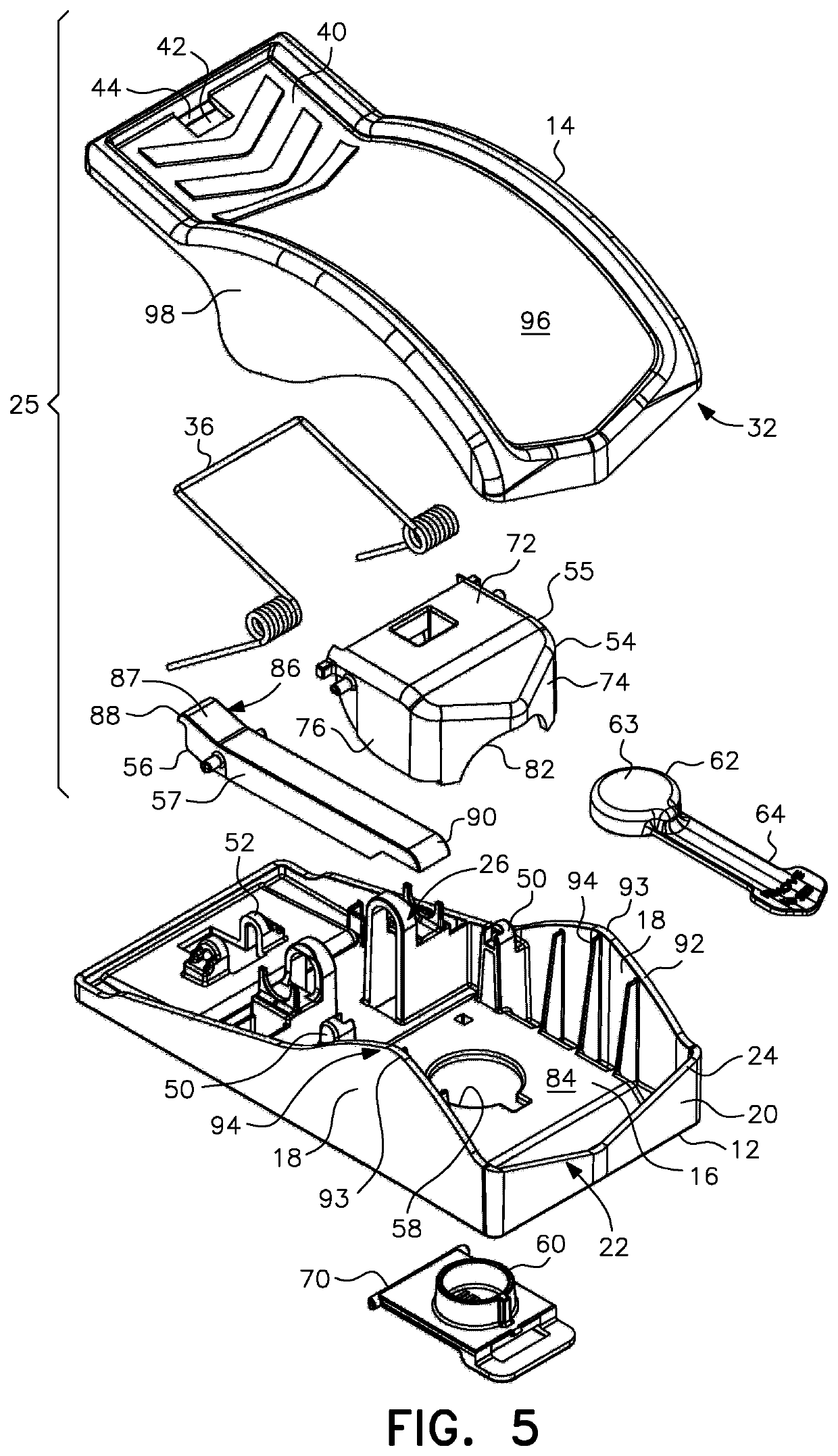
[0009]The pre-baited bait cup is preferably formed integrally with a bait door that is pivotally coupled to the bottom of the base, with the base including an opening through which the bait cup projects upwardly when the door is closed. When opened, the bait door swings downwardly, away from the bottom of the base while remaining hingedly connected thereto, to enable the bait cup to be refilled and then can be pivoted upwardly so that the bait cup protrudes through the opening and is positioned directly underneath the trigger hood. The free end of the door is secured in the closed position against a recessed surface on the underside of the base, preferably with a snap fit connection. The base is provided with two substantially mirror-image side walls that extend longitudinally from the front to the rear of the base. The height of the side walls is greater near the forward end of the base, with the upper edges of the side walls sloping upwardly from a front edge of the trap and then downwardly to form a peak positioned on either side of the bait cup. The height of the side walls and the positioning of the peaks, as well as the configuration of the trigger hood positioned over the bait cup, serve to properly orient the rodent for capture as the rodent can only access the bait from the front of the trap and must be sufficiently committed inside the trap, thereby producing optimal positioning between the upper and lower jaws upon trap activation.
[0021]Still yet a further object of the present invention is to provide a chip-clip style snap trap that is economical to manufacture and use, and robust and effective in operation.

Problems solved by technology

Due to the spring bias that must be overcome when pressing the setting ends of the jaws of a rodent snap trap together, chip-clip style snap traps can be difficult to set without finger slippage.
In addition, chip-clip style snap traps may be triggered when the rodent is not properly positioned relative to the jaws, increasing the number of rodent escapes.
A further problem can arise in connection with snap traps that are pre-baited with a quantity of bait covered by a seal or cap for freshness.
These traps can inadvertently be placed in a set position by the user without first removing the seal or bait cap, resulting in decreased rodent interaction with the trap.
In addition, re-baiting some pre-baited traps is complicated by difficulty accessing the bait cup or the potential loss of the bait cup in those designs where the bait cup is fully removed to add bait.
Finally, many chip-clip style snap traps are complex in structure, making them difficult and / or expensive to manufacture and assemble.

Method used


Image

  • Snap trap with set-prevent interference member and rodent orienting side walls
  • Snap trap with set-prevent interference member and rodent orienting side walls
  • Snap trap with set-prevent interference member and rodent orienting side walls

Examples


Embodiment Construction

[0037]It is to be understood that the embodiment described herein is disclosed by way of illustration only. It is not intended that the invention be limited in its scope to the details of construction and arrangement of components set forth in the following description or illustrated in the drawings. Also, in describing the preferred embodiments, specific terminology will be resorted to for the sake of clarity. It is to be understood that each specific term includes all technical equivalents which operate in a similar manner to accomplish a similar purpose.

[0038]As shown in the assembled views of FIGS. 1-4 and the exploded view of FIG. 5, the present invention is directed to a chip-clip style snap trap for rodents. The snap trap, generally designated by reference numeral 10, includes a base 12 and a top or lid 14 which form an aligned pair of clamping jaws. The base 12 includes a horizontal platform 16 with two matching vertically extending side walls 18 joined by an upwardly direct...


PUM


Abstract

A chip-clip type snap trap for rodents is provided that includes a bait cup covered by a bait cap that prevents setting of the trap when the bait cap is in place, high side walls to properly orient a rodent before trap activation, and grip elements on the lid and base to prevent finger slippage when setting the trap. The lid and base of the trap snap together without the need for pins, fasteners or tools, providing for easy and cost-effective manufacture.

Description

BACKGROUND OF THE INVENTIONField of the Invention[0001]The present invention is related to the field of rodent control and, more particularly, to a “chip-clip” style snap trap for rodents.Description of the Related Art[0002]Snap traps like the wooden VICTOR® brand mouse trap have been used effectively to capture mice for decades. More recently, molded plastic snap traps in various styles and sizes have become commercially available. These molded plastic snap traps include the “chip-clip” style trap that has upper and lower jaws that come together in a locking position at a trapping end to grip a mouse, the jaws being placed in the set position by squeezing the opposite ends of the jaws together to open the trapping end in an action like that of a clothespin or “chip clip” commonly used to temporarily close the open end of a bag of chips when the jaws are released to return the trapping end to the locking or closed position.[0003]Due to the spring bias that must be overcome when pres...

Claims


Application Information

Patent Timeline
Patent Type & Authority Patents(United States)
IPC IPC(8): A01M23/30A01M23/24
CPCA01M23/30A01M23/245
Inventor BLAIR, CORYADAMSON, MICHAELLUBIC, MARKO K.
Owner WOODSTREAM CORP
Learn More