
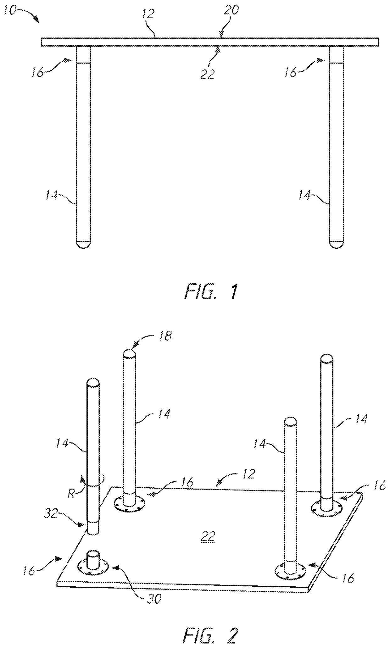
Table with removable legs

a technology of legs and tables, applied in the field of tables, can solve the problems of plastic deformation of the bolt or the material, additional loads and potential plastic deformation of the bolt or the nut, and the difficulty in achieving accurate collimation between the bolt and the nu

Active Publication Date: 2022-10-25
EXEMPLIS
View PDF25 Cites 3 Cited by
  • Summary
  • Abstract
  • Description
  • Claims
  • Application Information

AI Technical Summary

Benefits of technology

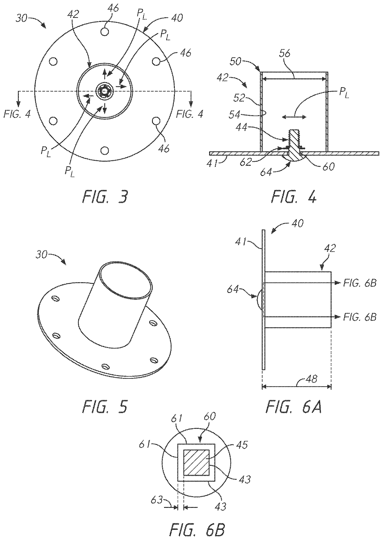
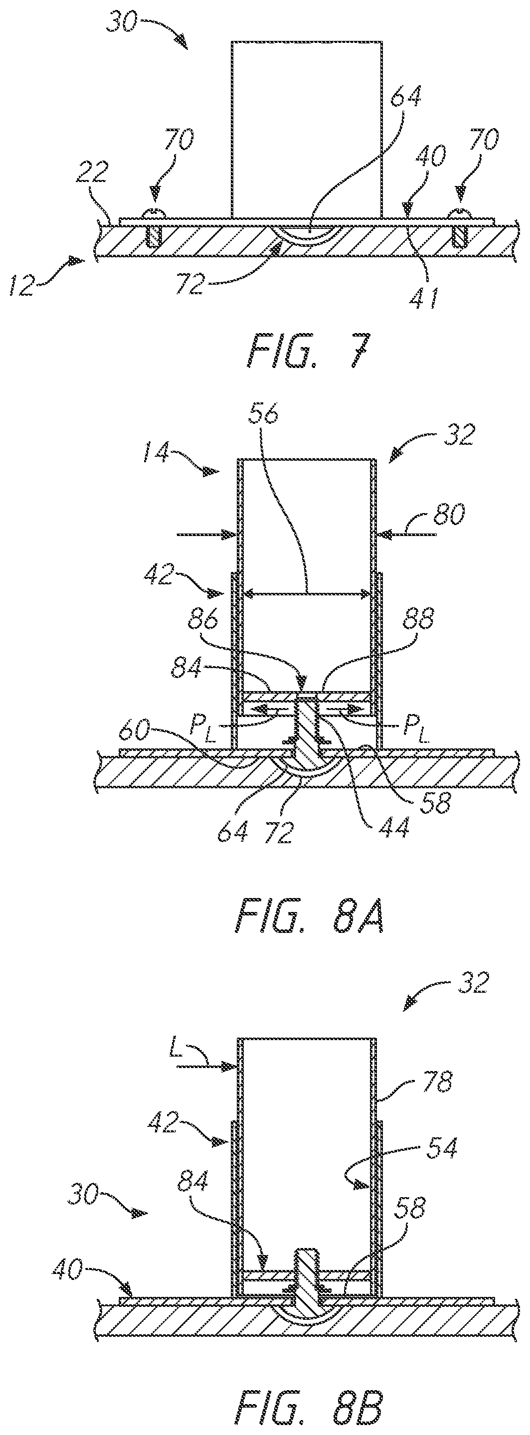
The invention provides a better design for mounting legs on furniture using threaded fasteners. The design reduces loads on the fasteners, improves alignment, and provides a more stable and secure connection between the leg and the socket. This leads to a reduction in potential plastic deformation and bolt or material misalignment.

Problems solved by technology

With both portions of the fastener, the bolt and the nut, secured in fixed locations and orientations relative to the socket and the leg, respectively, a collimation problem arises.
The collimation problem is due to the need to be able to align the bolt and the nut as well as the socket in the outer surface of the leg, with sufficient accuracy that the threads on the bolt and the nut can engage.
However, a close fit between the inner walls of the socket and the outer surface of the leg also make it more difficult to achieve accurate collimation between the bolt and the nut.
Along these lines, any misalignment of the bolt and / or nut can result in additional loads and potential plastic deformation of the bolt or of the material forming the fixed connection, such as adhesive or weld.
However, this shifting or bending can cause plastic deformation of the bolt itself and / or weaken the connection between the bolt and the socket.
Further, as the leg is loaded in use, for example, due to lateral loads, such loads can be imparted onto the connection between the bolt and the socket, thereby potentially causing additional plastic deformation and / or damage to the connection between the bolt and the socket.
This combination of loads can result in further plastic deformation or damage to the connection between the bolt and the socket.

Method used


Image

  • Table with removable legs
  • Table with removable legs
  • Table with removable legs

Examples


Embodiment Construction

[0062]The embodiments disclosed herein are described in the context of providing detachable attachment mechanisms for legs of pieces of furniture such as tables and desks because they have particular utility in that context. The inventions disclosed herein, however, can be used in other contexts as well, for example, but without limitation, for connecting legs to other types of furniture or devices, or for attaching other different pieces of furniture to one another, or for connecting other types of devices in other contexts.

[0063]Certain terms may be used in the following description for the purpose of reference only, and thus are not intended to be limiting. For example, terms such as “upper”, “lower”, “above”, and “below” refer to directions in the drawings to which reference is made. Terms such as “front”, “back”, “rear”, and “side” describe the orientation and / or location of portions of the component within a consistent but arbitrary frame of reference which is made clear by re...


PUM


Abstract

A furniture assembly can include a tabletop with removable legs. The removable legs can be attached to the tabletop with a socket having a threaded member mounted in a non-fixed and anti-rotation registration at the bottom of the socket. The legs can be mounted to the socket by insertion and turning for threaded engagement. The floating engagement mechanism can allow the threaded fastener member to move during installation to provide for enhanced alignability between the leg and the threaded fastener member.

Description

INCORPORATION BY REFERENCE TO ANY PRIORITY APPLICATIONS[0001]This application claims the benefit of U.S. Patent Provisional Application No. 63 / 094,282, filed Oct. 20, 2020, the entire contents of which are hereby expressly incorporated by reference herein in their entirety and for all purposes. In addition, any and all applications for which a foreign or domestic priority claim is identified in the Application Data Sheet as filed with the present application are hereby incorporated by reference under 37 CFR 1.57.BACKGROUND OF THE INVENTIONSField of the Inventions[0002]The embodiments disclosed herein relate to tables or other pieces of furniture with removable legs, including desks with legs that can be removed for shipping.Description of the Related Art[0003]Various different designs exist for removably mounting legs to furniture, including tables and desks. Such types furniture are usually supported by a plurality of legs resting on the floor, to support an upright support surface...

Claims


Application Information

Patent Timeline
Patent Type & Authority Patents(United States)
IPC IPC(8): A47B13/00
CPCA47B13/003A47B2013/006F16B12/44
Inventor DEVRIES, PAULJEFFERY, PETERSCHAFFER, SHANEDIBBLE, RYAN
Owner EXEMPLIS
Learn More