
Image reading device and image forming apparatus

a reading device and image technology, applied in the direction of electrographic process equipment, instruments, optics, etc., can solve the problems of increasing the size of the document feeder, and affecting the feeding of documents

Active Publication Date: 2022-11-15
SHARP KK
View PDF5 Cites 0 Cited by
  • Summary
  • Abstract
  • Description
  • Claims
  • Application Information

AI Technical Summary

Benefits of technology

This configuration effectively prevents distortion and maintains roller parallelism, ensuring accurate document feeding without the need for additional fastening members or increased weight, thus preventing skewed feeding.

Problems solved by technology

This causes distortion between the two side frames positioned across the center of gravity of the document feeder (in other words, one side frame tilts relative to the other side frame), and the parallelism of the multiple transport rollers supported by the two side frames is shifted, which may cause skewed feeding of the document.
To prevent such distortion between the front frame and the rear frame, the front frame and the rear frame must be firmly fastened with many more fastening members, which may result in an increase in the weight of the document feeder.
This increase in the weight of the document feeder leads to an increase in the urging force of the urging mechanism, which causes a need to reinforce the document feeder.
As a result, there is a risk of causing an increase in the size of the document feeder.

Method used


Image

  • Image reading device and image forming apparatus
  • Image reading device and image forming apparatus
  • Image reading device and image forming apparatus

Examples


first embodiment

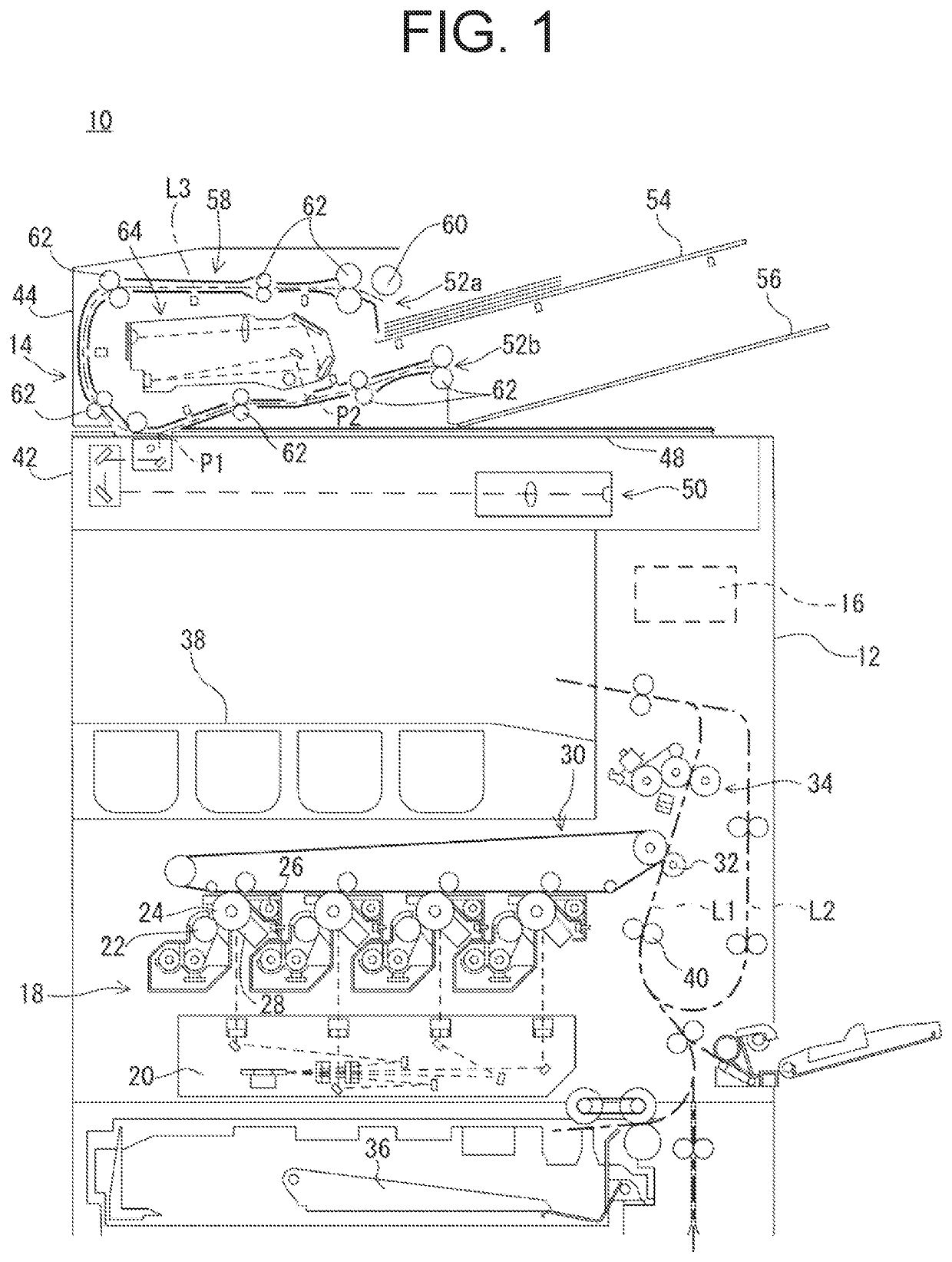
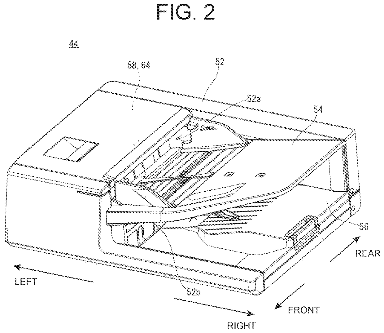
[0037]With reference to FIG. 1, an image reading device 14 of a first embodiment of the present invention includes a reading device body 42 and a document feeder 44 that can be opened and closed relative to the reading device body 42. The image reading device 14 is used in an image forming apparatus 10 that forms images on sheets by an electrophotographic method.

[0038]The basic configuration of the image forming apparatus 10 will now be briefly described. Note that in this specification, the front-back direction. (depth direction) of the image forming apparatus 10 and its components are defined such that the surface facing the user's standing position, that is, the surface on the side to which the operation panel (not illustrated) is disposed is the forward surface (front surface). The left-right direction (transverse directions) of the image forming apparatus 10 and its components are defined with reference to the state in which the image forming apparatus 10 is viewed from a user....

second embodiment

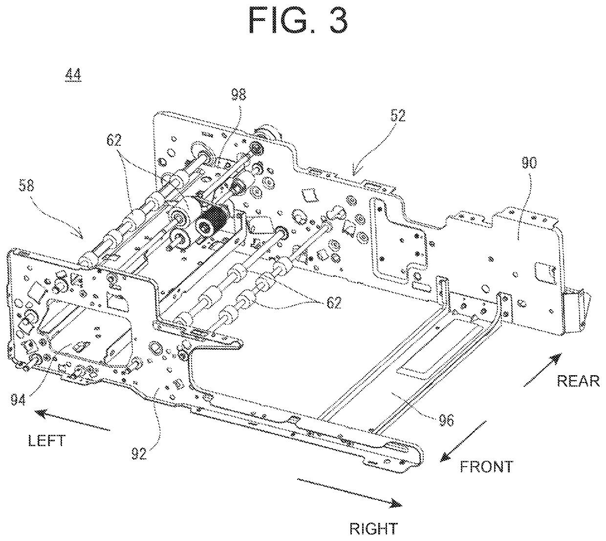
[0085]The image reading device 14 according to the second embodiment of the present invention will now be described. In the second embodiment, the configuration of the right beam frame 96 differs from that of the first embodiment described above. Since other parts are the same, descriptions that overlap with the first embodiment described above are omitted or simplified.

[0086]Although not illustrated, in the second embodiment, an extended portion is formed in the right beam frame 96 in addition to that is the left beam frame 94, and this extended portion is coupled (fixed) to a frame fixing member of the right hinge device. As the extended portion of the right beam frame 96 and the frame fixing member of the right hinge device, those having the same configuration as those of the left, beam frame 94 and the left hinge device 46 may be employed.

[0087]According to the second embodiment, the distortion between the rear frame 90 and the front frame 92 can be prevented more reliably becau...


PUM


Abstract

An image reading device includes a reading device body and a document feeder that is turnably attached on the upper side of the reading device body with hinge devices. An extended portion that extends outward from a rear frame is formed on a beam frame fixing the rear frame and a front frame of the document feeder at a predetermined interval, and a third coupling portion coupled to the turning member of the hinge device is formed in the extended portion.

Description

BACKGROUND OF THE INVENTIONField of the Invention[0001]This invention relates to an image reading device and an image forming apparatus, and in particular, for example, to an image reading device and an image forming apparatus, wherein a document feeder is turnably attached to the upper side of the reading device body having an image device section using a hinge device.Description of the Background Art[0002]Japanese Unexamined Patent Publication No. 2003-228141 discloses an example of a known image forming apparatus. The image forming apparatus of JP 2003-228141 includes a document transporter (document feeder), an image reader (reading device body), a frame of the document transporter, a panel to which the frame and a transporting drive system are attached, and a hinge (hinge device) that allows the document transporter to be opened and closed relative to the image reader. The hinge includes a fixed member that is fixed to the image reader and a movable member (turning member) that...

Claims


Application Information

Patent Timeline
Patent Type & Authority Patents(United States)
IPC IPC(8): H04N1/00G03G21/00G03G15/00
CPCG03G15/602G03G15/6511G03G15/6529G03G21/1628H04N1/0053H04N1/00535H04N1/00554
Inventor NISHIMURA, TOSHIKI
Owner SHARP KK
Learn More