Projection screen apparatus including holographic optical element

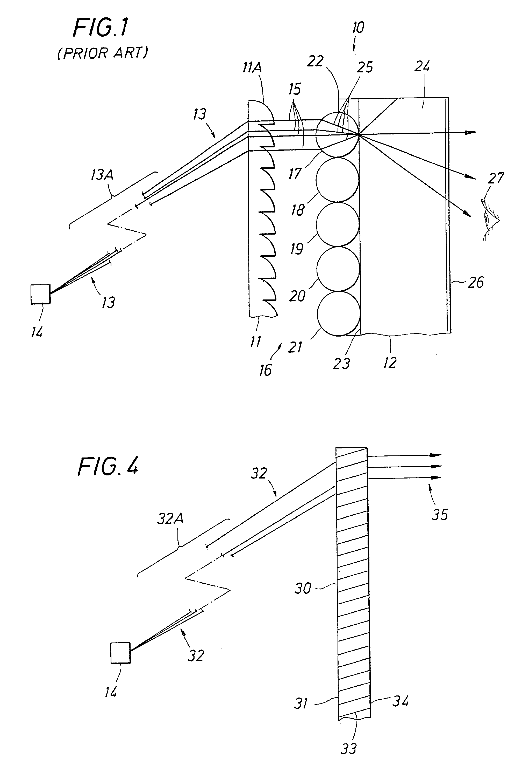
a technology of projection screen and optical element, which is applied in the direction of optics, projectors, instruments, etc., can solve the problems of degrading display image, no satisfactory methods of collimating light at the display screen, and disadvantage of fresnel lens 11

Inactive Publication Date: 2001-05-24
CHI MEI MATERIALS TECH CORP
View PDF0 Cites 27 Cited by
  • Summary
  • Abstract
  • Description
  • Claims
  • Application Information

AI Technical Summary

Problems solved by technology

For wide angle projection, there are currently no satisfactory methods of collimating light at a display screen.
The conventional Fresnel lens 11 may create objectionable shadows and ghosts (i.e., ghost images from light scattered in undesired directions) that degrade the display image.
Moreover, the Fresnel lens 11 is also disadvantageous because it may be relatively expensive, easily damaged, have visible rings, and cannot be laminated (e.g., index matched) on both sides.
Removing the Fresnel lens 11 and relying only on the diffusive screen 12 itself to achieve uniformity may result in a "hot spot" in the center of the screen and wasted light diffused out of the field of view of the viewer 27.

Method used


Image

  • Projection screen apparatus including holographic optical element
  • Projection screen apparatus including holographic optical element
  • Projection screen apparatus including holographic optical element

Examples


first embodiment

[0026] The present invention relates to an improved screen apparatus, for example, a projection screen, that may be employed in a front or rear projection system, such as a television, or in a computer monitor. Referring to FIGS. 4 and 5, a holographic optical element (HOE) 30 is included in a screen apparatus 40 (FIG. 5) in accordance with the invention. The HOE 30 may be used to replace the Fresnel lens 11 discussed above, performs a similar function as the Fresnel lens 11, but has distinct advantages that will be described below. The HOE 30 is recorded and processed (e.g., developed and possibly baked) to substantially collimate incoming image light 32 received from the image engine 14. Baking may be required for certain HOE (e.g., photopolymer) materials used to make the HOE 30, such as some materials that can be obtained from DuPont. Other types of HOE materials used to make the HOE 30, such as those for making surface relief, surface kineform, or embossed HOEs, may employ othe...

second embodiment

[0034] Referring to FIG. 7, a screen apparatus 100 is illustrated in accordance with the invention. The screen apparatus 100 includes the HOE 30 layered or coated on, bonded or adjacent to, or otherwise suitably applied to, a diffusive screen or diffuser 102. Suitable bonding may be achieved with an index matching optical adhesive or material (not shown) applied between the surface 34 of the HOE 30 and a first surface 104 of the diffuser 102, as will be appreciated by those skilled in the art. The diffuser 102 may be formed of a mixture of any two (or more) appropriate immiscible materials having different indices of refraction. An example of such materials could be two immiscible polymers that have indices of refraction n=1.5 and n'=1.52, respectively. Another possible material for the diffuser 102 includes TiO.sub.2 or other like materials that, when dispersed as particles or particulate clusters of appropriate size in polymer materials (e.g., a polymer matrix), such as acrylic or...

third embodiment

[0039] Reference is now made to FIGS. 10 and 11 for an implementation of the screen apparatus 150 in accordance with the invention. As will be appreciated by those of skill in the art of holography, modifications of the optical setup shown in FIG. 6 can be made that make it possible to record a hologram that converges (or diverges in other embodiments) light instead of collimating light. This can be accomplished, for example, by moving the lens 60 relative to the spatial filter 58 and the photosensitive material 62. Once recorded with reference and object beams as interference fringes 133, and then developed and possibly baked, as discussed above, the converging hologram (the remaining discussion will emphasize converging light instead of diverging light) could be repositioned in its original position with respect to the same or a similar reference beam for reproducing the converging object beam. In FIG. 10, such a hologram is shown as an HOE 130, which is positioned to receive imag...


PUM


Abstract

A screen apparatus includes a holographic optical element and a diffuser. The holographic optical element may be constructed using standard techniques known in the field of holography. The holographic optical element may be used to replace a typical Fresnel lens used in projection screen apparatuses. In operation, the holographic optical element receives image light from an image engine or projector and redirects the image light to the diffuser for scattering. The holographic optical element can be designed to substantially collimate. converge, or diverge the image light. The combination of the holographic optical element and the diffuser provides improved illumination uniformity that can be perceived by a viewer as the viewer moves in directions transverse to the screen apparatus. The screen apparatus may be designed to provide improved illumination uniformity to optimized or optimal locations in a viewing region. The screen apparatus may be advantageously employed in display apparatuses.

Description

[0001] 1. Field of the Invention[0002] The present invention relates to projection systems and projection screens and, more particularly, to a projection screen apparatus that provides improved image illumination uniformity.[0003] 2. Description of Related Art[0004] Light projection is used to display images on large surfaces, such as large computer displays or television screens. In front projection systems, an image beam is projected from an image source onto the front side of a reflection-type, angle transforming screen, which then reflects the light toward a viewer positioned in front of the screen. In a rear projection system, the image beam is projected onto the rear side of a transmission-type, angle transforming screen and transmitted toward a viewer located in front of the screen.[0005] Referring to FIG. 1, wide angle projection systems that include a screen apparatus 10 are known to optimally use a conventional Fresnel lens 11 in combination with some diffusing element, su...

Claims


Application Information

Patent Timeline
Patent Type & Authority Applications(United States)
IPC IPC(8): G03B21/62
CPCG02B5/1876G02B5/1885G03B21/625
Inventor WALKER, DALE S.
Owner CHI MEI MATERIALS TECH CORP
Why Eureka
Try Eureka