This helps you quickly interpret patents by identifying the three key elements:
Problems solved by technology
Method used
Benefits of technology
Benefits of technology
[0005] The present invention responds to the above shortcoming, and aims to present a fitting detecting connector in which the locking arm returns smoothly to its original position when the two connector housings have been correctly fitted together.
Problems solved by technology
However, as shown in FIG. 20, when the locking arm d rises over the stopping protrusion b and returns to its original position, the resilient spring force of the coiled springs f is sometimes exerted from the restraining wall g of the spring holder e towards the tip of the locking arm d, as shown by the arrow in FIG. 20, thus regulating the return of the locking arm d. That is, there is the possibility that locking cannot occur even though the two housings a and c have been correctly fitted together, and thus further improvement is required.
Method used
Image
Click on the blue label to locate the original text in one second.
Reading with bidirectional positioning of images and text.
Examples
first embodiment
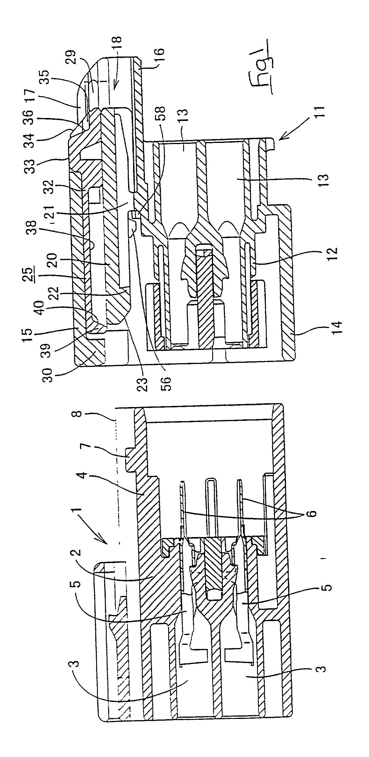
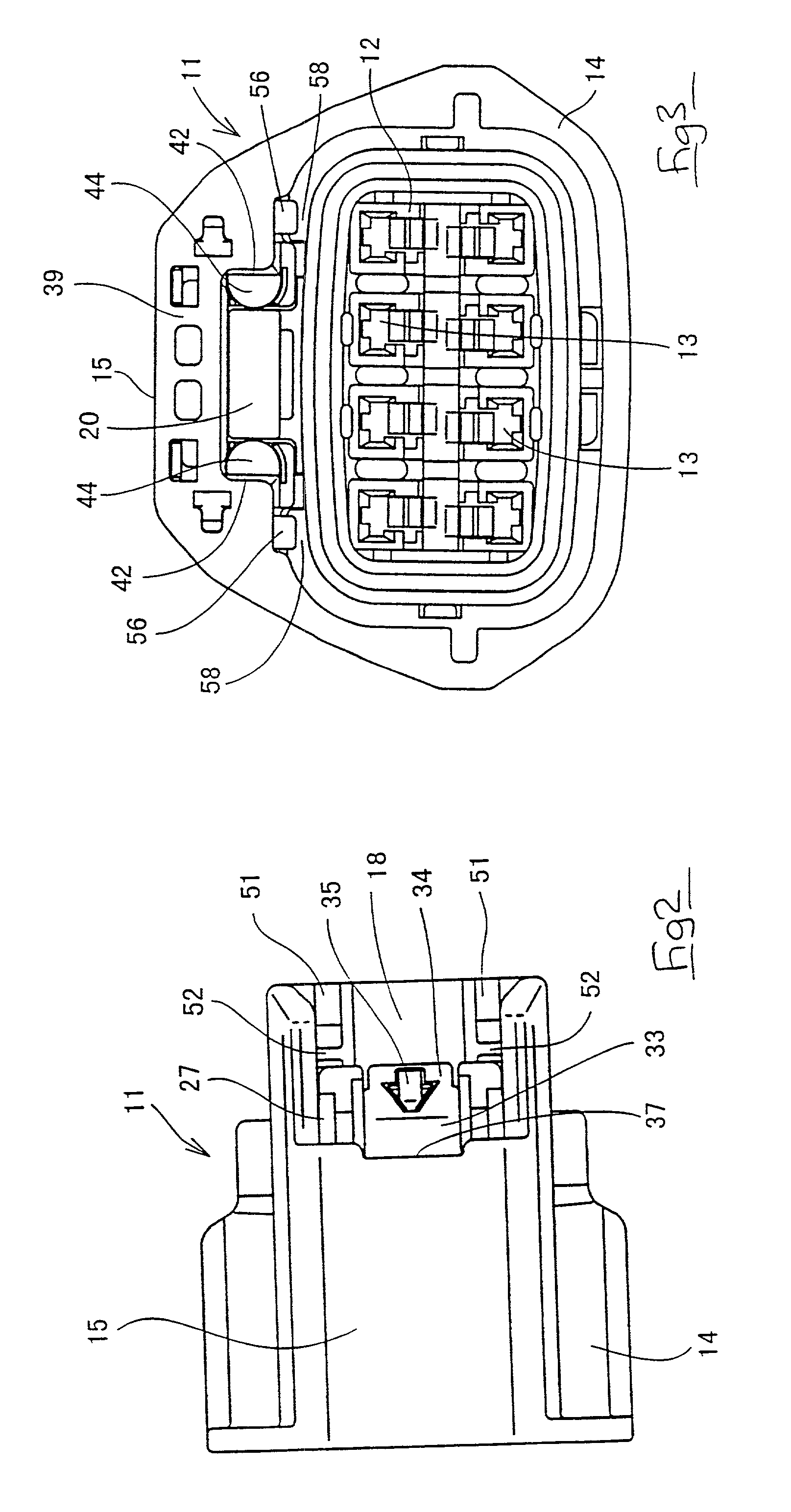
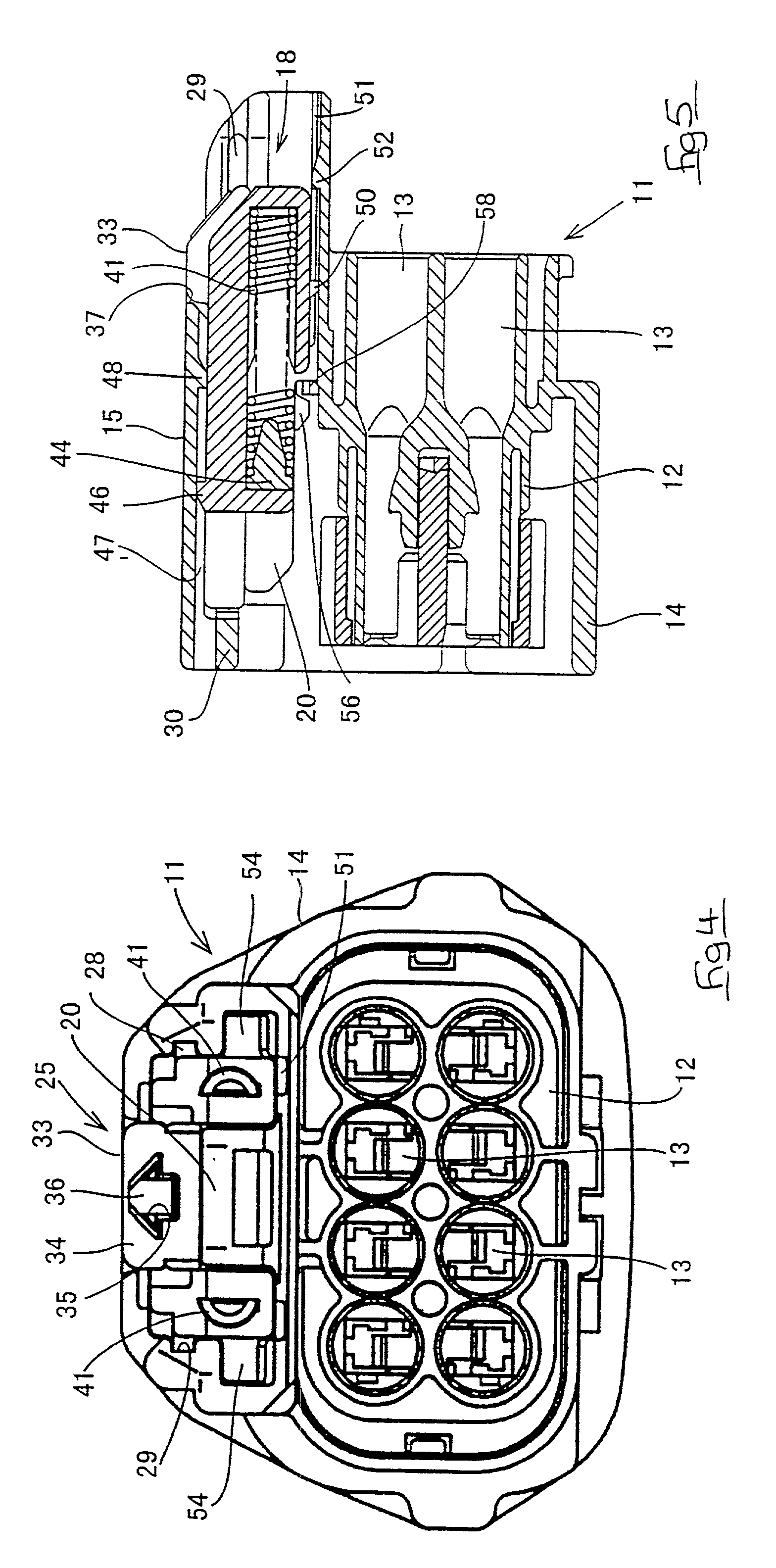
[0028] the present invention is described below with the aid of FIGS. 1 to 16. As FIG. 1 shows, this embodiment is provided with a male connector housing 1 (hereafter referred to as male housing) fitting with a female connector housing 11 (hereafter referred to as female housing). Mutually fitting faces of the housings 1 and 11 will be considered to be anterior faces.
[0029] The male housing 1 is made from plastic and is part of an electrical apparatus (not shown). Eight cavities 3 are formed as two upper and lower layers in a main member 2 of the male housing 1, and an angular tubular fitting cylinder 4 is formed on an anterior face of the main member 2. Male terminal fittings 5 are inserted into each cavity 3, tabs 6 of these male terminal fittings 5 protruding into the fitting cylinder 4 and being housed therein in a state that prevents removal. A stopping protrusion 7 is formed on an upper face of the fitting cylinder 4 at a location close to an anterior edge thereof, a pair of l...
third embodiment
[0057] For this reason, in the third embodiment, the contacting face provided on the restraining wall 30 of the spring holder 25 consists of two steps having differing angles of inclination, these being tapered faces 63 and 64. That is, if the bending of the locking arm 20 is large, the locking arm 20 makes contact with the upper tapered face 63, and the angle .alpha. with respect to the direction of compression of the coiled springs 41 will be larger. When contact is made with the lower tapered face 64, the angle .beta. with respect to the direction of compression of the coiled springs 41 will be smaller.
[0058] According to this configuration, if the bending of the locking arm 20 is large when it rises over the stopping protrusion 7, the locking arm 20 will make contact with the upper tapered face 63 having the large angle .alpha.. As the fitting operation of the two housings 1 and 11 continues, the resilient returning force of the coiled springs 41 will gradually increase but, sin...
second embodiment
[0061] Moreover, if a tapered face is provided on the anterior end face of the locking arm 20, as in the second embodiment, this face will consist of two steps having differing angles of inclination and identical operation and effects will be obtained. That is, the two steps are arranged so that when the bending of the locking arm 20 is large, the angle relative to the direction of compression of the coiled springs 41 will be large at the lower step on the anterior end face of the locking arm 20, this lower step making contact with the restraining wall 39; and when the bending of the locking arm 20 is small, the upper step making contact with the restraining wall 39 is inclined so that a small angle is formed relative to the direction of compression of the coiled springs 41.
[0062] Furthermore, the present invention is not limited to the embodiments described above with the aid of figures. For example, the possibilities described below also lie within the technical range of the prese...
PUM
Abstract
A spring holder 25 containing coiled springs 41 is installed in a female housing 11. When a male housing 1 and this female housing 11 are fitted together, a locking arm 20 rises over a stopping protrusion 7, a restraining wall 39 simultaneously engages a locking claw 22, and the coiled springs are compressed. The locking claw 22 makes contact with a contacting face of the restraining wall 39, this contacting face being a tapered face 40. When the locking arm 20 is about to pass over the stopping protrusion 7 to return to its original position, the restraining wall 39 receives a spring force F from the coiled springs and pushes the locking arm 20. A component force F1 in a returning direction of the locking arm 20 is obtained from this spring force F due to the tapered face 40. The component force F1 and the returning force of the locking arm 20 itself cause the locking arm 20 to return smoothly, and the locking arm 20 thus engages with the stopping protrusion 7.
Description
[0001] The present invention relates to a fitting detecting connector.BACKGROUND TO THE INVENTION[0002] Disclosed in JP-9-211020 is a fitting detecting connector in which, when male and female connector housings are not correctly fitted together, force from a spring pushes the housings apart, and in which a locking arm is provided on one of the connector housings, this locking arm maintaining the two connector housings and the spring in a fitted state.[0003] The configuration of this fitting detecting connector is explained briefly below with the aid of FIG. 19. A male housing a fitting together with a female housing c has a stopping protrusion b. The corresponding female housing c has a bendable locking arm d for engagement by the stopping protrusion b and a spring holder e capable of being moved in an anterior-posterior direction. Coiled springs f are housed within this spring holder e, these coiled springs f being compressed by an anterior edge of the male housing a. When the two...
Claims
Application Information
Patent Timeline
Application Date:The date an application was filed.
Publication Date:The date a patent or application was officially published.
First Publication Date:The earliest publication date of a patent with the same application number.
Issue Date:Publication date of the patent grant document.
PCT Entry Date:The Entry date of PCT National Phase.
Estimated Expiry Date:The statutory expiry date of a patent right according to the Patent Law, and it is the longest term of protection that the patent right can achieve without the termination of the patent right due to other reasons(Term extension factor has been taken into account ).
Invalid Date:Actual expiry date is based on effective date or publication date of legal transaction data of invalid patent.
Patent Type & AuthorityApplications(United States)

