A co-combustion device for biomass and coal circulating fluidized bed controlled by jet flow

A circulating fluidized bed and biomass technology, which is applied in the directions of fluidized bed combustion equipment, fuels burned in a molten state, and combustion methods, etc., can solve problems such as limited supply, difficulty in maintaining normal operation of biomass burning enterprises alone, and corrosion. , to reduce carbon dioxide, promote combustion reaction and heat transfer, and improve reaction efficiency

Active Publication Date: 2011-12-14
NORTH CHINA ELECTRIC POWER UNIV (BAODING)
View PDF5 Cites 11 Cited by
  • Summary
  • Abstract
  • Description
  • Claims
  • Application Information

AI Technical Summary

Problems solved by technology

However, compared with European and American countries, domestic biomass resources are relatively scattered, and the supply as a commodity is very limited. Therefore, most of the domestic market applications are small and medium-capacity boilers, and due to the constraints of raw material seasonality and geographical radius, production is forced to It is difficult for enterprises that burn materials alone to maintain normal operation without policy support. Only enterprises that use waste biomass resources such as timber factories and rice mills have their living space
From a technical point of view, the problems of deposition, slagging, and corrosion in the process of biomass combustion have not been well resolved. For the use of fluidized bed combustion boilers, it is necessary to further study the influence of particle flow non-uniformity in the furnace on the combustion and heat transfer process. influence behavior

Method used


Image

  • A co-combustion device for biomass and coal circulating fluidized bed controlled by jet flow
  • A co-combustion device for biomass and coal circulating fluidized bed controlled by jet flow

Examples


Embodiment Construction

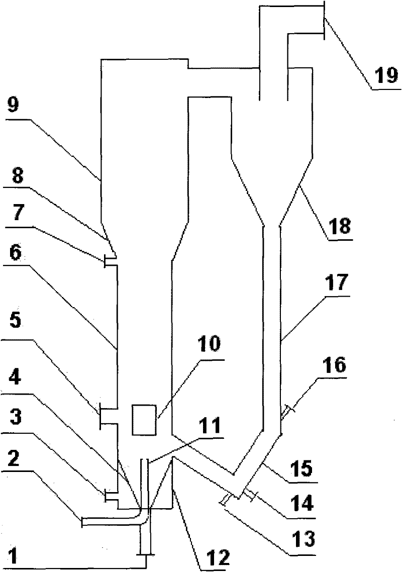
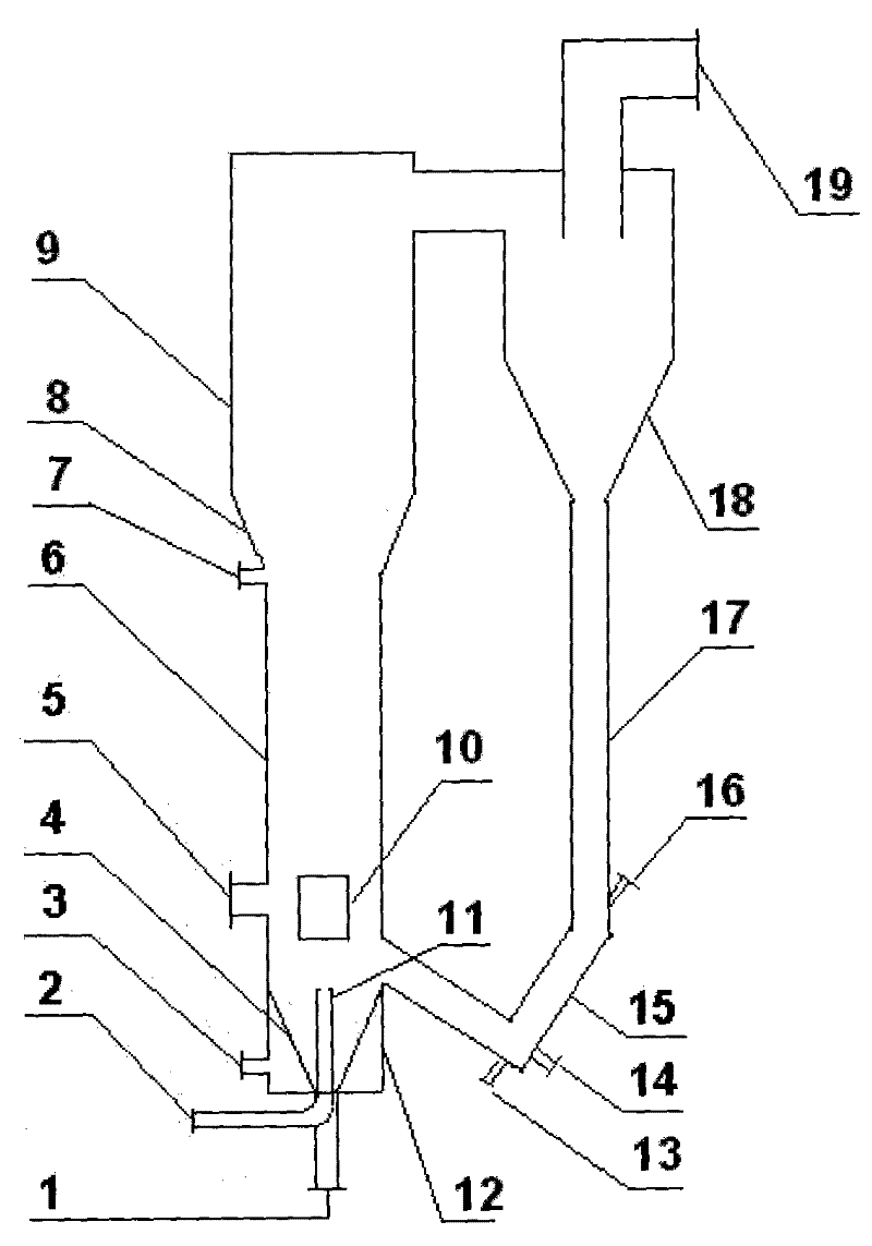
[0020] Biomass is pneumatically conveyed by oxygen-enriched air and enters the lower bed body 6 of the fluidized bed through the biomass jet feed pipe 2, forming a continuous jet flow above the biomass jet feed pipe 2, and the raw coal enters through the raw coal inlet 5, and is connected with the The biomass forms a countercurrent movement, and under the disturbance of the jet flow, the biomass and coal are completely mixed, and the oxygen-enriched air enters the bed through the primary air inlet 3 and the gas distributor 4, so that the entire bed is in a stable fluidized state. Biomass and coal undergo a combustion exothermic reaction under the action of oxygen-enriched air, and the biomass is heated to generate biomass oil, which is further cracked into small molecule combustible gas by the biomass tar cracker 10, and together with the gas generated by coal combustion, entrains a large amount of ash Slag, unburned coal particles, semi-coke, etc. move upward from the lower pa...


PUM


Abstract

A biomass and coal composite burner is composed of a fluidized bed (7), a biomass jet inlet pipe (2), an oxygen-rich air inlet (3), a gas distributor (4), a feed coal inlet (5), a fluidized bed heat conduction pipe (6), a heat exchanger (9), a heat exchanger heat conduction pipe (10), a cyclone separator (8), an ash outlet (1), an oxygen-poor air outlet (11) and an ash discharge outlet (12), and is characterized in that the bottom of the fluidized bed (7) is equipped with the ash outlet (1), the jet inlet pipe (2) and the gas distributor (4), the lower portion is equipped with the heat conduction pipe (6), the side surface is provided with the feed coal inlet (5), and the upper portion is equipped with the cyclone separator (8); the bottom of the heat exchanger (9) is provided with the ash discharge outlet (12), the lower portion is equipped with the oxygen-poor air outlet (11), and the heat conduction pipe (10) is disposed inside heat exchanger. After biomass is transferred by oxygen-rich air into the fluidized bed (7), biomass and coal are rapidly mixed under the action of jet and then combust, thus greatly minimizing the generation of biomass tar.

Description

technical field [0001] The invention relates to a combustion device of solid fuel, in particular to a co-combustion device of biomass and coal circulating fluidized bed controlled by jet flow. Background technique [0002] Biomass has great compatibility with traditional fossil fuels such as coal and oil. It is not only easy to connect with the existing energy industry in terms of power generation and heat supply utilization, but also is the only renewable resource that can be directly converted into carbon-containing fuels. In December 2009, the International Energy Agency pointed out in a report on biomass energy that currently renewable energy provides 13% of the world's primary energy, while biomass plays a dominant role in renewable energy, accounting for about 10%. Biomass energy accounts for about 3% in developing countries, mainly used for power generation and heat supply; but in developing countries, the average is about 22%, and some countries even reach more than ...

Claims


Application Information

Patent Timeline
Patent Type & Authority Applications(China)
IPC IPC(8): F23C10/10C10J3/60
CPCY02E20/34
Inventor 张锴陈宏刚张凯华滕阳杨勇平
Owner NORTH CHINA ELECTRIC POWER UNIV (BAODING)
Why Eureka
Try Eureka