Light scanner with cylindrical lenses

a technology of light scanners and cylindrical lenses, applied in the direction of non-linear optics, picture reproducers using projection devices, instruments, etc., can solve the problems of low quality, difficult to achieve uniform scanning for all color components in a single scanning element, and less light efficient removal of color filter solutions so far. achieve non-linear scanning, maintain scan quality, and wide input aperture

Inactive Publication Date: 2001-11-08
KONINKLIJKE PHILIPS ELECTRONICS NV
View PDF0 Cites 47 Cited by
  • Summary
  • Abstract
  • Description
  • Claims
  • Application Information

AI Technical Summary

Benefits of technology

[0022] According to the present invention, the scan non-linearities caused by the use of a single prism to scan all three colors (RGB) in a single panel scrolling raster display system are reduced and / or corrected by employing static cylindrical lenses to prefocus and postfocus the static color stripe pattern passing through a scanning element, in a manner to achieve the correct scan function for all ray heights of the input pattern. Thus, the outer rays of color stripe pattern entering the scanning prism will undergo the same scrolling function as the center rays of the color stripe pattern, maintaining scan quality over a wide input aperture.

Problems solved by technology

The moving color filter solutions so far have been less light efficient because they tend to discard at least two thirds of the available white light to achieve individual color components.
However, in these dichroic mirror systems, the problem is then in designing a scanning mechanism that converts the static color stripes into a useful scrolling color stripe pattern.
It suffers, however, from low quality imaging of the color stripes, and it is generally very difficult to achieve uniform scanning for all color components in a single scanning element.
This means that the scanner has to perform a different geometrical transformation for different incoming ray heights, or aberrations will result in the scrolling light band output.
The correction is, however, incomplete.
Because the apparatus scans by employing an angularly deflected beam, telecentric behavior of the beam (constant angle of incidence) is lost.
The scan angle of this system is rather limited.
The angular displacement is also limited in this system.

Method used


Image

  • Light scanner with cylindrical lenses
  • Light scanner with cylindrical lenses
  • Light scanner with cylindrical lenses

Examples


example 1

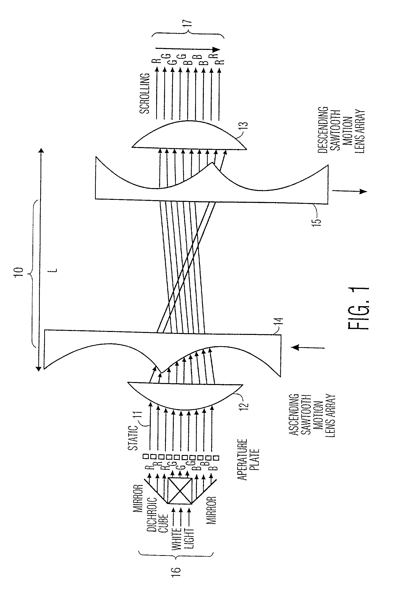
[0058] A first embodiment of the invention, shown in FIG. 1, uses a static cylindrical lens 12 to prefocus the static color-stripe pattern 11 into the scanning element 10. This makes it possible to achieve the correct scan function for all input ray heights; the height difference is translated into a phase pre-correction for the actual scanning element 10. A postfocus cylinder lens 13 is then used to back convert the translation after the actual scanning function by the scanning element 10.

[0059] FIG. I shows an embodiment where the scanning element 10 itself consists of two arrays 14, 15 of negative cylinder lenses that move in opposite directions. The static positive prefocus 12 and postfocus 13 lenses, and the moving negative lenses 14, 15, all have a focal length approximately equal to the distance L between input and output. For ideal lenses, all very close to the respective input and output planes, the focal length should be equal to distance L. In practice, however, lenses ar...

example 2

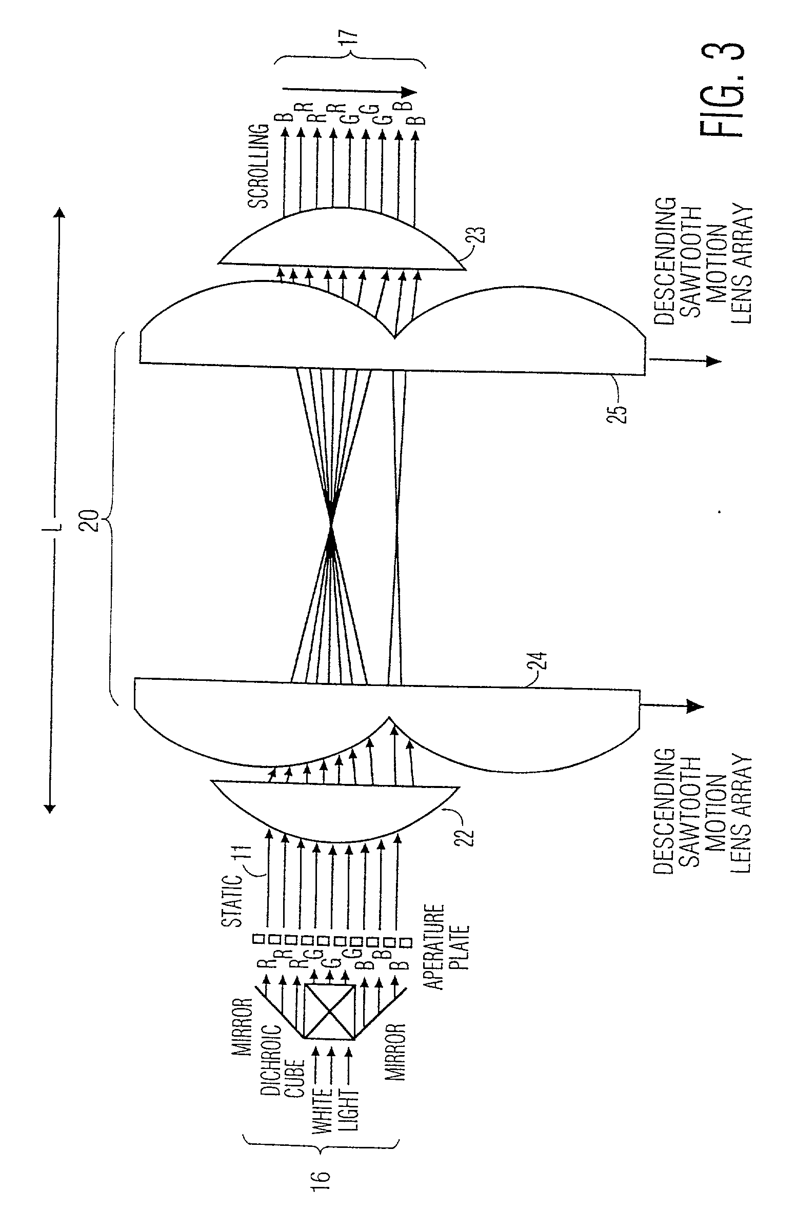
[0062] FIG. 3 shows a second embodiment of the invention wherein the scanning element 20 itself consists of two arrays of positive cylinder lenses 22, 23 that move in the same direction. Again, the static prefocus lens 22, the postfocus lens 23, and the two arrays of moving lenses 24, 25 all have a focal length approximately equal to the distance L between input and output, and the array lenses 22, 23 have a size equal to the input and output beam aperture. The mechanism is very similar to that described with respect to FIG. 1, but now the input light pattern is effectively output up-side-down.

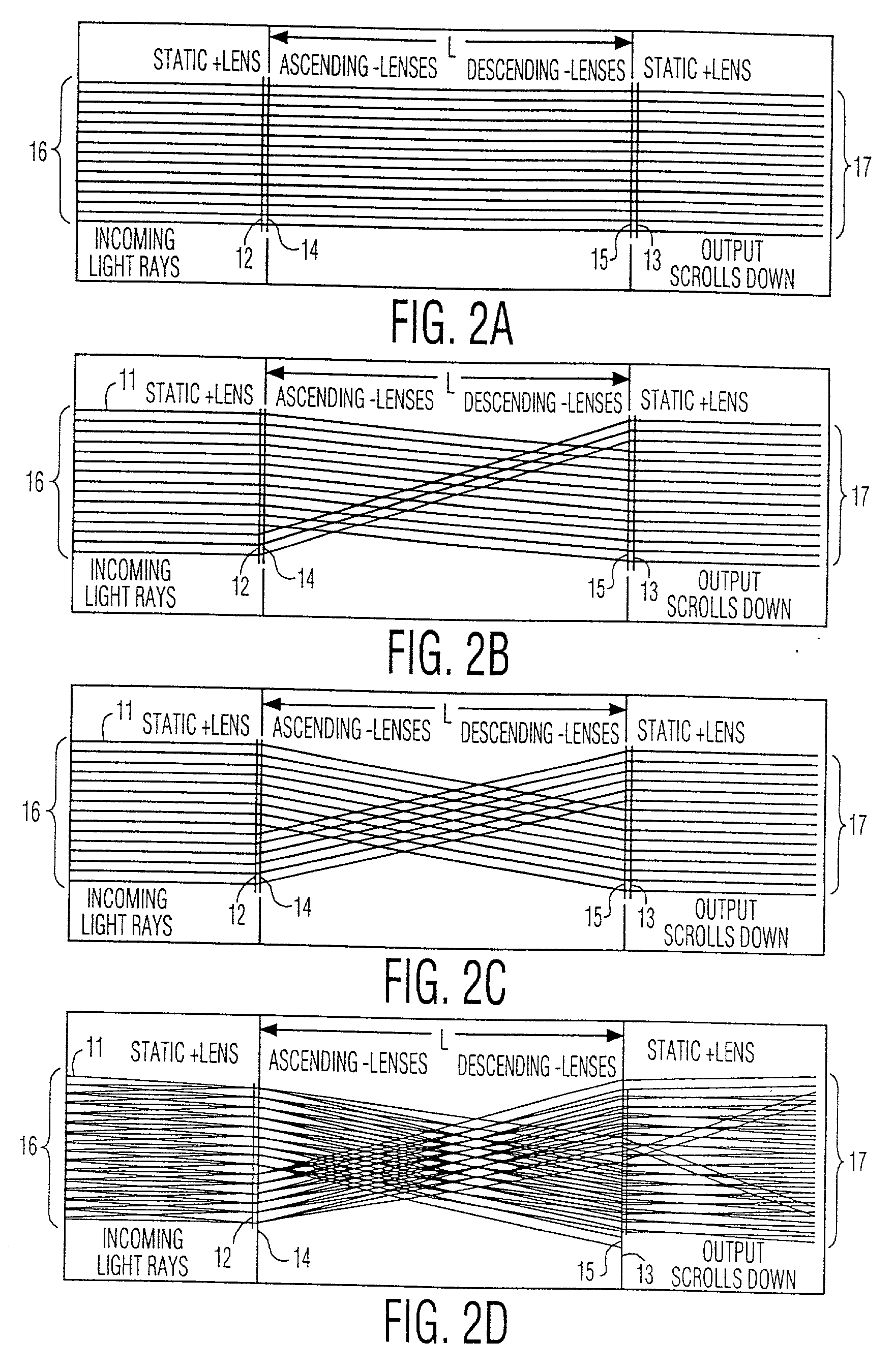
[0063] FIGS. 4A, 4B and 4C show the scan function at three different points in time. FIG. 4A shows the situation where all four lens elements 22, 23, 24, 25 are perfectly aligned. FIGS. 4B and 4C illustrate the scan function for equal but opposite shifts of the arrays 24, 25.

[0064] FIG. 4D shows the effect of a finite opening angle (divergence) of the input beam. Some rays that correspond to t...

example 3

[0065] FIG. 5 shows a third embodiment of the invention, in which, for a system with positive cylinder lens arrays, as described above with respect to FIG. 3, an internal relay lens array 26 can be added that eliminates the problem of loss of outer edges of the input beam. The added center array 26 moves at half the speed, has half the lens size, and a four times shorter focal length than the other lenses in the system 22, 23, 24, 25. For synchronous linear array movement and ideal lenses, the output light pattern is now fully independent of the input ray angle for telecentric beam opening angles up to the cone that corresponds to the full input and output aperture (array lens size) at input to output distance, as shown in FIG. 6.

[0066] Although the scanner transfer function as described above in Examples 1, 2 and 3 is in principle ideal, a linear lens-array movement does not lend itself easily to continuously scrolling systems. Depending on the details of the application, the linea...


PUM

PropertyMeasurementUnit
total angleaaaaaaaaaa
aperture angleaaaaaaaaaa

Abstract

A scrolling scan optical band scanner is provided having a scrolling scan optic with a scan function that inherently deviates from an ideal imaging function over wide apertures. Compensation optics are provided to correct the scrolling scan optic performance to provide accurate imaging over a wide aperture. The compensation optics and the scrolling scan optic together accurately scroll the input pattern to an output pattern according to the formula:<paragraph lvl="0"><in-line-formula>x0(t) / X=(t / T+x1 / X) modulo 1,< / in-line-formula>with X being the total height of input and output beam, xi being the ray height in the input beam, x0 being the corresponding ray height in the output beam as a function of time, T being the frame period, and t being the time, and said scroll patterns remains telecentric even where X is large with respect to a physical size of the scanning optic system.

Description

[0001] The present invention relates to improved scroll scanning systems, and in particular, to systems which provide imaging of scrolling multiple color bands across a single-panel reflective or transmissive display device in a video projector.[0002] A known color projection display system includes a monochromatic flat panel display device that is, in operation, sequentially illuminated with light. The modulated light pattern from the display device is then projected onto a display surface. For color projection, monochromatic light sources or selectively filtered light sources are sequentially scanned over the flat panel display device at a repetition rate sufficient that the human eye perceives a single color image. The human eye thus integrates this "color sequential" display of three separate images into a "single" image. By providing a single flat panel display device, a common optical path is provided for all colors, and convergence and misregistration errors are substantially...

Claims


Application Information

Patent Timeline
Patent Type & Authority Applications(United States)
IPC IPC(8): G02B3/00G02B3/06G02B13/24G02B26/08G02B26/10G02B27/00G02F1/13G02F1/1335G02F1/13357G03B21/00G03B21/14H04N9/31
CPCG02B26/0875G02B26/108H04N9/3117H04N9/3197
Inventor LAMBERT, NICOLAAS
Owner KONINKLIJKE PHILIPS ELECTRONICS NV
Why Eureka
Try Eureka