Light scanner with cylindrical lenses
- Summary
- Abstract
- Description
- Claims
- Application Information
AI Technical Summary
Benefits of technology
Problems solved by technology
Method used
Image
Examples
first embodiment
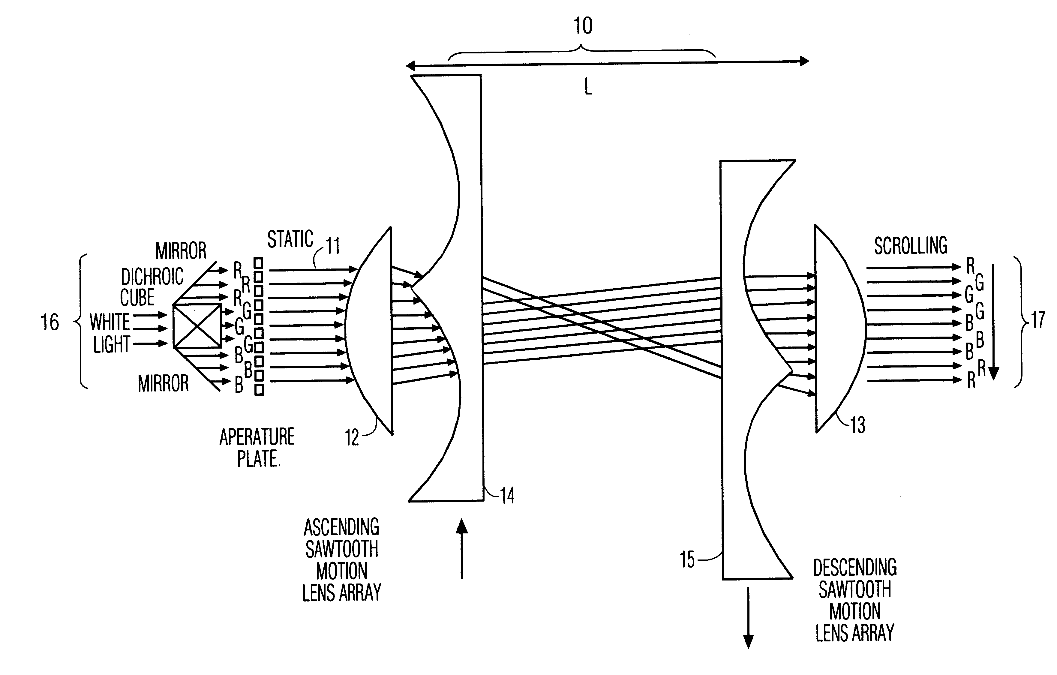
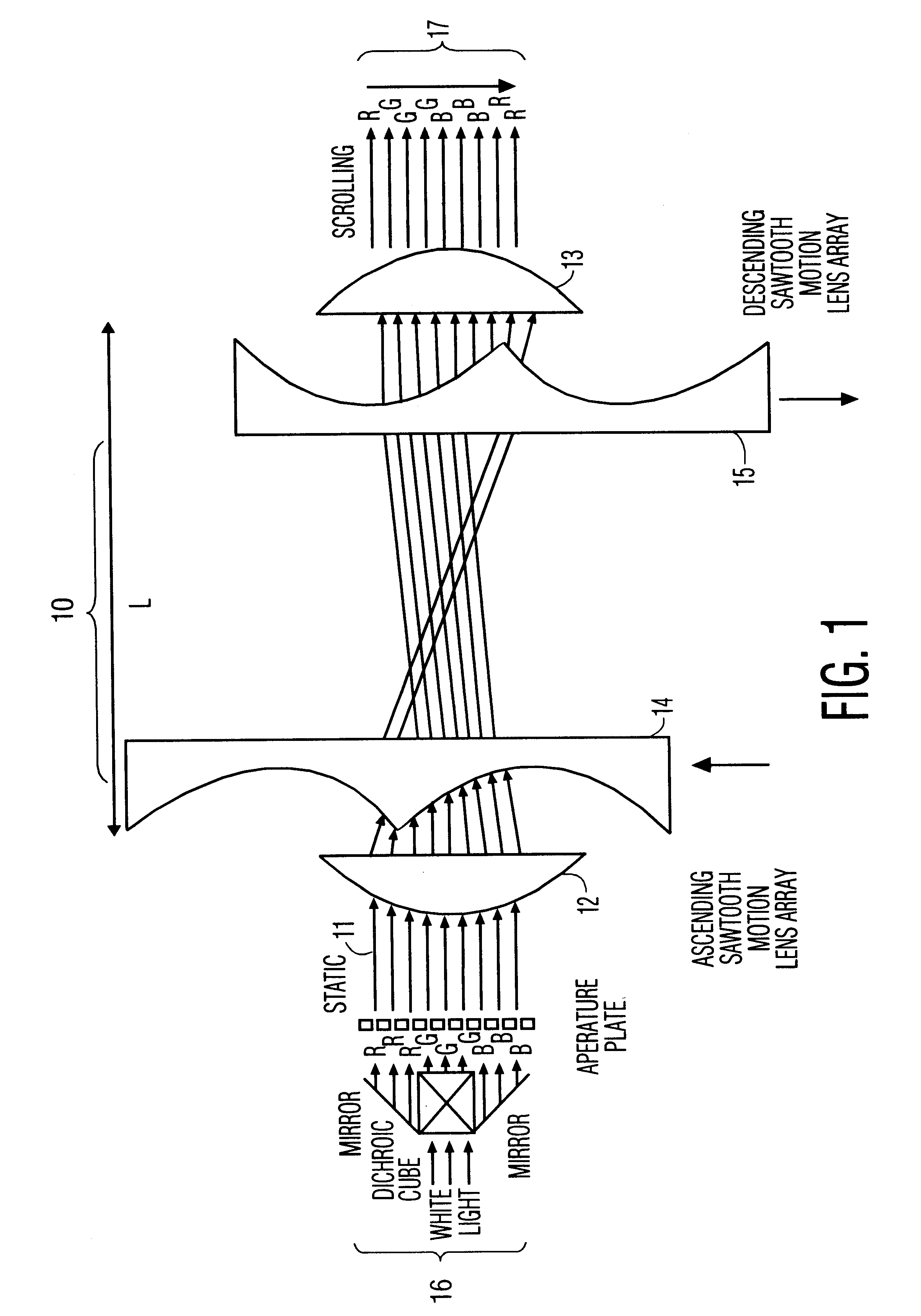
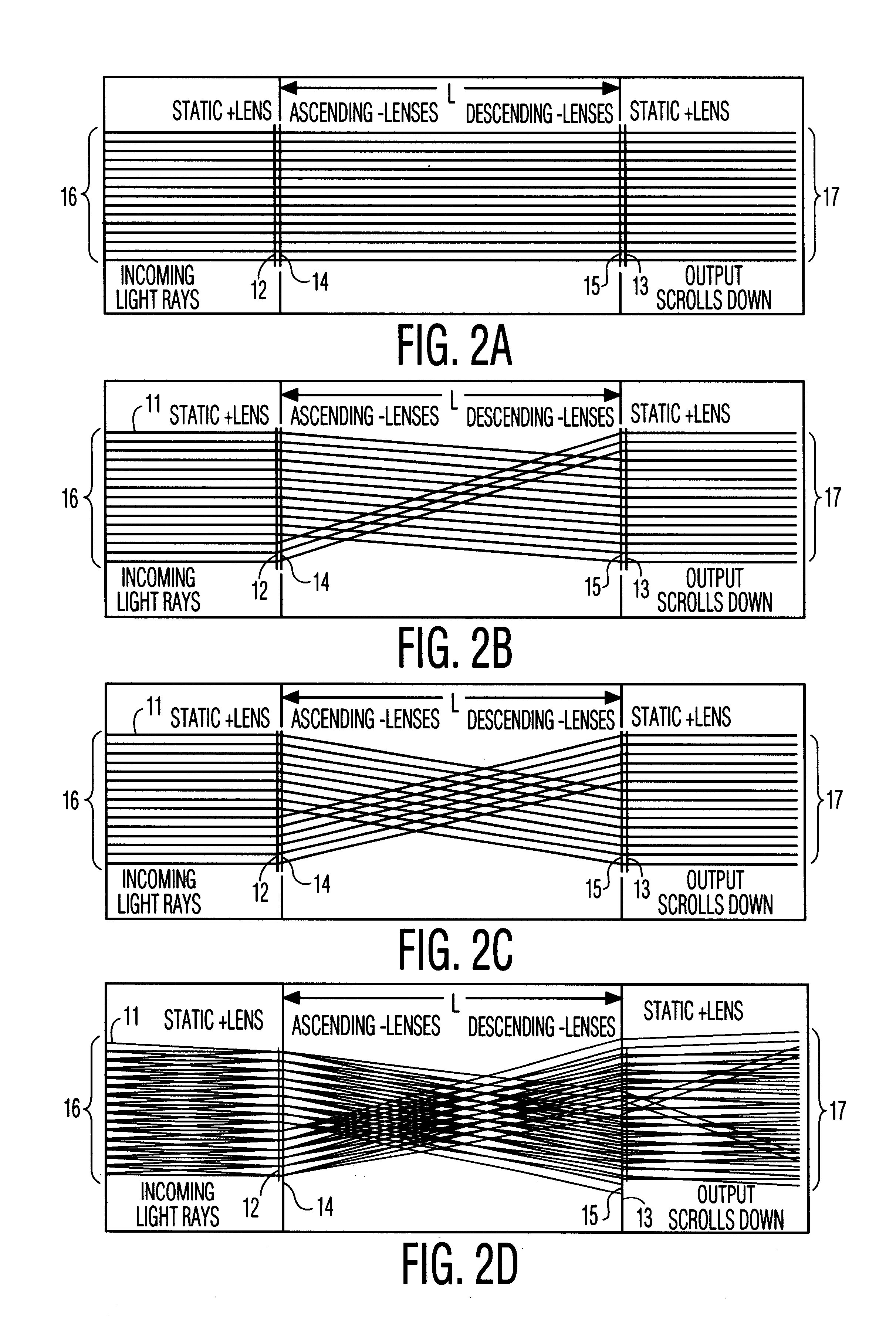
the invention, shown in FIG. 1, uses a static cylindrical lens 12 to prefocus the static color-stripe pattern 11 into the scanning element 10. This makes it possible to achieve the correct scan function for all input ray heights; the height difference is translated into a phase pre-correction for the actual scanning element 10. A postfocus cylinder lens 13 is then used to back convert the translation after the actual scanning function by the scanning element 10.
FIG. 1 shows an embodiment where the scanning element 10 itself consists of two arrays 14, 15 of negative cylinder lenses that move in opposite directions. The static positive prefocus 12 and postfocus 13 lenses, and the moving negative lenses 14, 15, all have a focal length approximately equal to the distance L between input and output. For ideal lenses, all very close to the respective input and output planes, the focal length should be equal to distance L. In practice, however, lenses are not perfect, have to be separated ...
example 2
FIG. 3 shows a second embodiment of the invention wherein the scanning element 20 itself consists of two arrays of positive cylinder lenses 22, 23 that move in the same direction. Again, the static prefocus lens 22, the postfocus lens 23, and the two arrays of moving lenses 24, 25 all have a focal length approximately equal to the distance L between input and output, and the array lenses 22, 23 have a size equal to the input and output beam aperture. The mechanism is very similar to that described with respect to FIG. 1, but now the input light pattern is effectively output up-side-down.
FIGS. 4A, 4B and 4C show the scan function at three different points in time. FIG. 4A shows the situation where all four lens elements 22, 23, 24, 25 are perfectly aligned. FIGS. 4B and 4C illustrate the scan function for equal but opposite shifts of the arrays 24, 25.
FIG. 4D shows the effect of a finite opening angle (divergence) of the input beam. Some rays that correspond to the outer edges of the...
example 3
FIG. 5 shows a third embodiment of the invention, in which, for a system with positive cylinder lens arrays, as described above with respect to FIG. 3, an internal relay lens array 26 can be added that eliminates the problem of loss of outer edges of the input beam. The added center array 26 moves at half the speed, has half the lens size, and a four times shorter focal length than the other lenses in the system 22, 23, 24, 25. For synchronous linear array movement and ideal lenses, the output light pattern is now fully independent of the input ray angle for telecentric beam opening angles up to the cone that corresponds to the full input and output aperture (array lens size) at input to output distance, as shown in FIG. 6.
Although the scanner transfer function as described above in Examples 1, 2 and 3 is in principle ideal, a linear lens-array movement does not lend itself easily to continuously scrolling systems. Depending on the details of the application, the linear movement can...
PUM
 Abstract
Description
Claims
Application Information
 - R&D
- Intellectual Property
- Life Sciences
- Materials
- Tech Scout
- Unparalleled Data Quality
- Higher Quality Content
- 60% Fewer Hallucinations
Browse by: Latest US Patents, China's latest patents, Technical Efficacy Thesaurus, Application Domain, Technology Topic, Popular Technical Reports.
© 2025 PatSnap. All rights reserved.Legal|Privacy policy|Modern Slavery Act Transparency Statement|Sitemap|About US| Contact US: help@patsnap.com


