
Golf club head and a method for manufacturing the same

Inactive Publication Date: 2001-12-06
ADVANCED INT MULTITECH CO LTD
View PDF0 Cites 244 Cited by
  • Summary
  • Abstract
  • Description
  • Claims
  • Application Information

AI Technical Summary

Problems solved by technology

However, because the conventional golf club head is always made of metal and the weight of the golf club head is standardized, the area of the face of the golf club head is limited.

Method used


Image

  • Golf club head and a method for manufacturing the same
  • Golf club head and a method for manufacturing the same
  • Golf club head and a method for manufacturing the same

Examples


Embodiment Construction

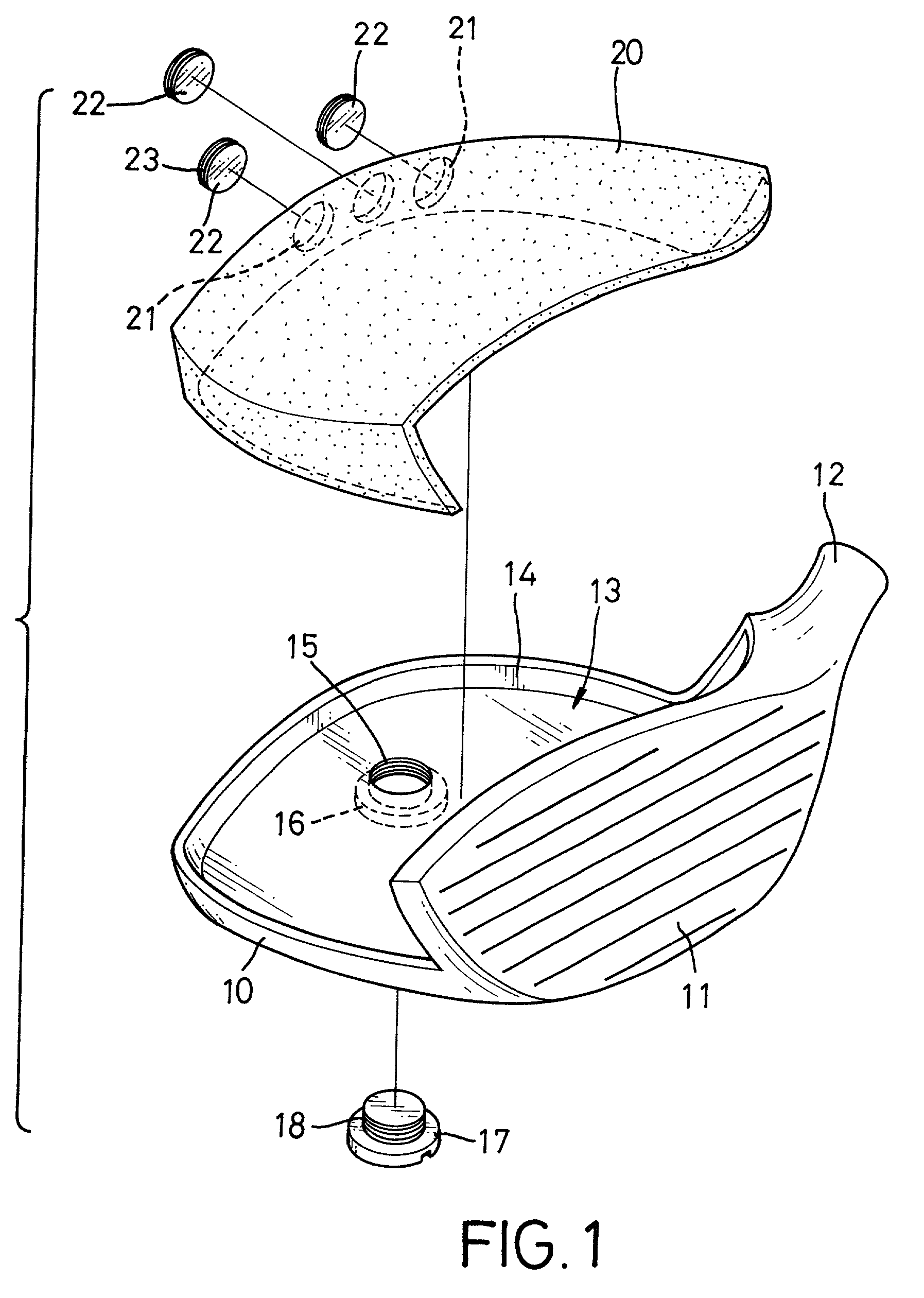
[0012] With reference to FIG. 1, a golf club head in accordance with the present invention comprises a base (10), a face (11), a neck (12) and a cover (20). The base (10) is made of metal. A countersunk threaded hole (15) is defined in the base (10). A countersunk recess (16) is defined in the base (10) around the threaded hole (15). A threaded plug (18) with an enlarged head (17) is screwed into the threaded hole (15). Consequently, the threaded plug (18) is securely attached to the base (10) due to the engagement with the threaded hole (15).

[0013] The face (11) extends up vertically from one edge of the base (10). Grooves are defined on the outside of the face (11). The neck (12) is a tubular member and is integrally connected to the base (10) and the face (11). A lip (14) is formed around the edges of the base (10) to form a cavity (13) between the base (10), the lip (14) and the face (11).

[0014] The cover (20) is securely attached to the lip (14) and the face (11) to cover the c...


PUM

PropertyMeasurementUnit
Sizeaaaaaaaaaa
Shapeaaaaaaaaaa

Abstract

A golf club head has a metal base, face and tubular neck and a carbon-fiber cover. The face extends up vertically from one edge of the base. The tubular neck is integrally connected to the base and the face. The cover is made of a carbon-fiber material and is securely attached to the base and the face. Because the carbon-fiber material is lighter than metal, the area of the face is enlarged. In addition, the shock absorbing effect of the golf head club is also improved.

Description

[0001] 1. Field of the Invention[0002] The present invention relates to a golf club head and the method for forming the same, and more particularly to a golf club head with a large hitting face and good flexibility.[0003] 2. Description of Related Art[0004] In general, one of two ways are usually used to manufacture a golf club head. One is to form the head with a cast mold process, and the other is to weld several parts together. However, because the conventional golf club head is always made of metal and the weight of the golf club head is standardized, the area of the face of the golf club head is limited. A new golfer easily misses the golf ball with a golf club having a conventional head. In addition, the shock absorbing effect of the conventional golf club head formed by combining several parts is easily reduced because of the welding process.[0005] To overcome the shortcomings, the present invention tends to provide an improved golf club head to mitigate or obviate the aforem...

Claims


Application Information

Patent Timeline
IPC IPC(8): A63B53/04A63B53/06A63B102/32
CPCA63B53/04Y10T29/49799A63B2053/0491A63B2053/0437A63B2209/02A63B53/0466A63B2053/0433Y10T29/49984Y10T29/49947Y10T29/49888Y10T29/49861Y10T29/49886Y10T29/49989Y10T29/49986A63B59/0092A63B60/54A63B53/0437A63B53/0433A63B60/02A63B60/00
Inventor CHENG, BERNARDCHEN, HSIAO-KUNCHIU, JEN-HUNG
Owner ADVANCED INT MULTITECH CO LTD
Learn More