Granular objects sorting apparatus

Inactive Publication Date: 2002-01-24
SATAKE CORPORATION
View PDF0 Cites 27 Cited by
  • Summary
  • Abstract
  • Description
  • Claims
  • Application Information

AI Technical Summary

Problems solved by technology

However, since the solenoid has such a construction that either one of the retracting or projecting-out operation of the reciprocating axis thereof is dependent on such a resilient member as a coil spring, there is a limit in response performance of the retracting and projecting-out operation of the reciprocating axis.
For this reason, in the case where such solenoid is used as an ejecting means, there is an inevitable limit in the sorting performance.
However, in the case where the granular objects to be ejected by a given

Method used


Image

  • Granular objects sorting apparatus
  • Granular objects sorting apparatus
  • Granular objects sorting apparatus

Examples


Example

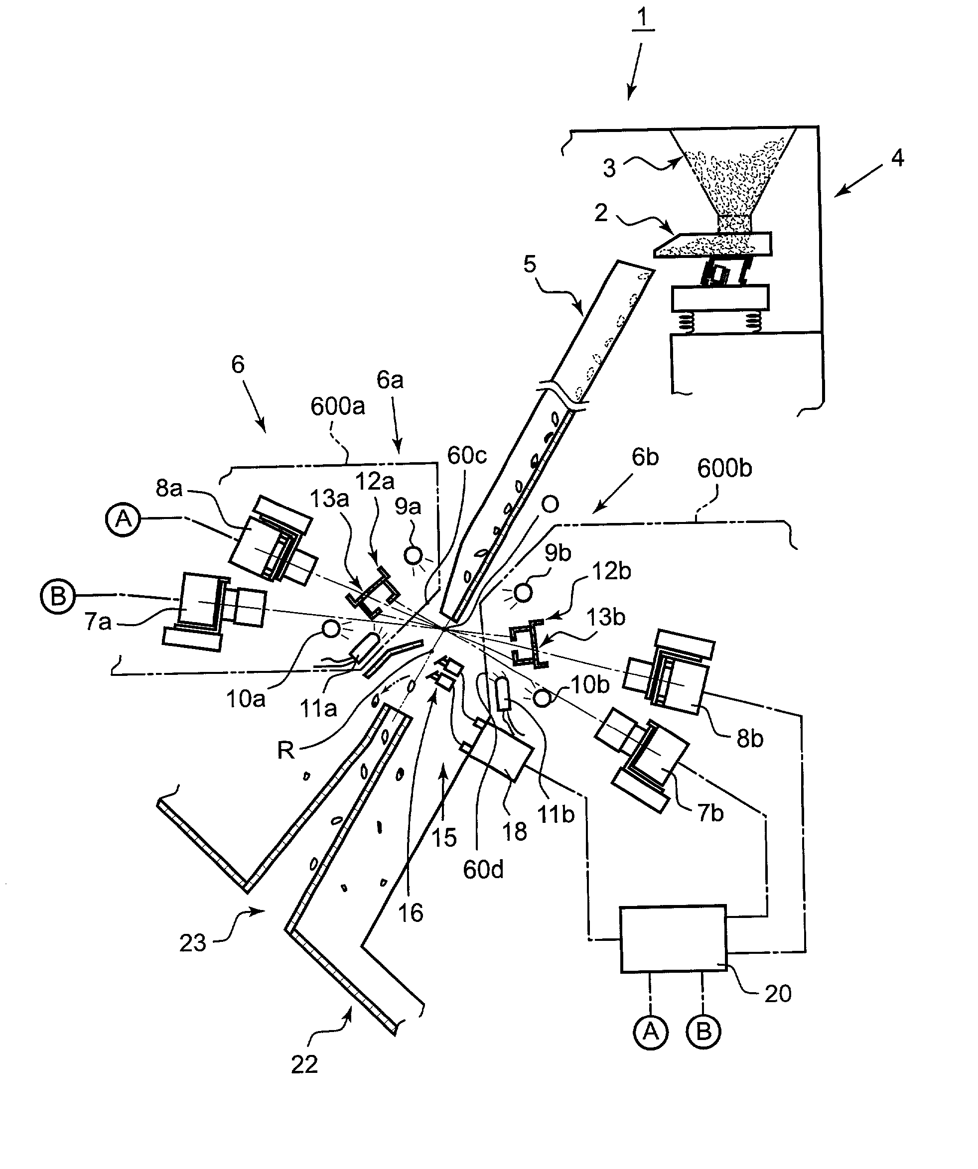
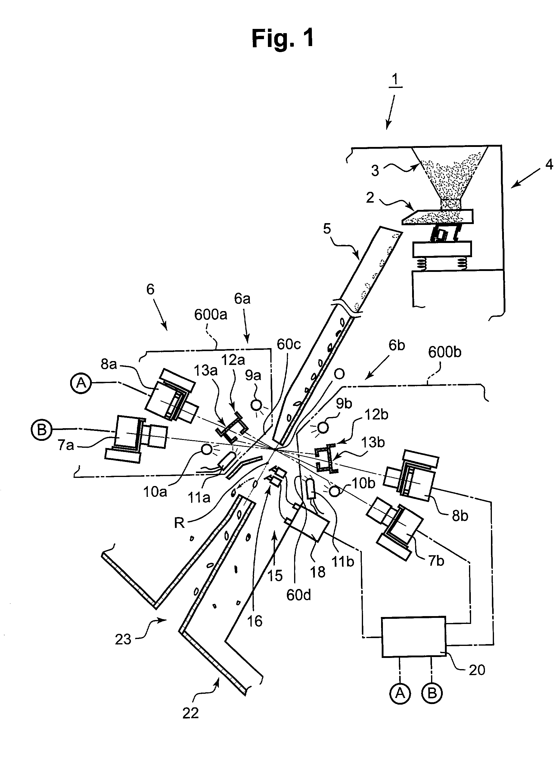
[0030] The outline of the granular object sorting apparatus according to the present invention is explained with reference to FIGS. 1 and 2. The sorting apparatus explained herein is one in which, for grains among granular objects, especially rice grains as raw materials to be sorted, the sorting or ejection is made for rice grains having colored portions or foreign objects mixed in the rice grains. FIG. 1 is a sectional view diagrammatically showing main elements and their internal structural arrangement of the granular object sorting apparatus 1. The apparatus is equipped, at its upper portion thereof, with a rice grain supplying section 4 which is formed by a vibration feeder means 2 and a tank section 3, and a chute 5 which is in an inclined plate-like form and transfers to a predetermined falling locus the rice grains supplied from the vibration feeder means 2. The rice grains thus transferred by this chute 5 are then released to an optical detecting section 6 to follow.

[0031] ...


PUM


Abstract

A reciprocating axis of the ejector is born in a non-sliding state by permanent magnets on the reciprocating axis and permanent magnets surrounding the reciprocating axis. The reciprocating axis linearly projects out and retracts by the reciprocating components which cause the reciprocating axis to reciprocate by the driving signals from the driver circuit. A slanted surface is provided at the foremost end of the reciprocating axis. When the granular objects to be ejected flow-in continuously, the projecting-out action takes place correspondingly with the leading granular object to be ejected and, after the following granular object(s) to be ejected has been ejected, the retracting action takes place.

Description

[0001] 1. Field of the Invention[0002] The present invention relates to a granular object sorting apparatus for sorting out a particular granular object wherein diffusion light from granular objects of raw materials to be sorted is received and each object is subjected to the determination as to whether it is acceptable or unacceptable based on the received diffusion light. More specifically, the present invention relates to an ejection means used in such sorting apparatus.[0003] 2. Description of the Related Art[0004] Japanese Patent Application Kokai-Publication No. Hei 9-113454 discloses an ejection means for a grain sorting apparatus, which is constructed by a plate spring means arranged at a point downstream of a point where the grains are image-taken by a CCD camera and divided into a plurality of plate sections along a transverse direction with respect to the falling locus of the grains; a plurality of solenoid means for deforming corresponding plate sections of the plate spr...

Claims


Application Information

Patent Timeline
IPC IPC(8): G01N21/85B07C5/342B07C5/36
CPCB07C5/3425B07C5/366Y10S209/908
Inventor SATAKE, SATORUSATAKE, TOSHIKOFUKUMORI, TAKESHI
Owner SATAKE CORPORATION
Why Eureka
Try Eureka