System and method for calculating an optimum display size for a visual object

a visual object and display size technology, applied in the field of system and method for calculating an optimum display size for a visual object, can solve the problems of lack of detail in quantization effects in audio, blockage, mosquito noise,

Inactive Publication Date: 2002-03-07
ARRIS GROUP
View PDF30 Cites 28 Cited by
  • Summary
  • Abstract
  • Description
  • Claims
  • Application Information

AI Technical Summary

Problems solved by technology

While the aforementioned compression techniques may permit the transmission of visual objects over a computer network, such compression techniques can introduce artifacts or distortion in the video as a direct result of the compression techniques.
For example, MPEG-1 encoding can introduce artifacts such as blockiness, mosquito noise, color bleeding, and shimmering effects within the video in addition to a lack of detail in quantization effects in audio.
While the effects of the compression techniques on the video segments of a multimedia presentation may be negligible in some instances, typically the artifacts and distortion generated by the compression techniques become quite apparent to a user when a visual object such as video is enlarged on a display device.
Therefore, some conventional media players do not even permit the selection for enlarging a video segment.
In addition to compression related artifacts discussed above, there also exists packet loss related artifacts that are a result of the transmission speed of a multimedia segment.
For example, low bit rates can also contribute to the artifacts or distortion when compressed video is decoded.
However, as noted above, a balance should be struck between displaying a visual object large enough to be comfortably viewed by a user while at the same time, displaying the visual object at a size that does not permit image degradations due to compression or transmission to be noticeable or easily perceived by the user.

Method used


Image

  • System and method for calculating an optimum display size for a visual object
  • System and method for calculating an optimum display size for a visual object
  • System and method for calculating an optimum display size for a visual object

Examples


Embodiment Construction

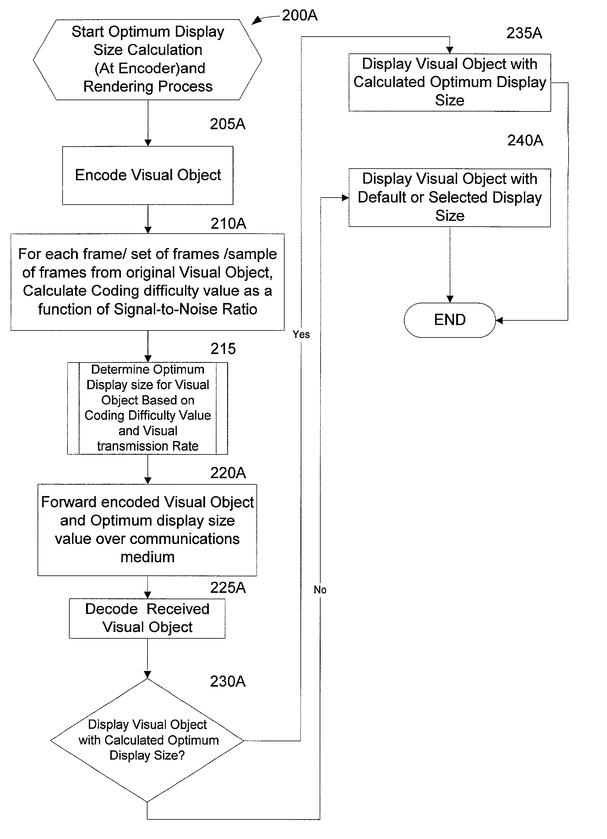
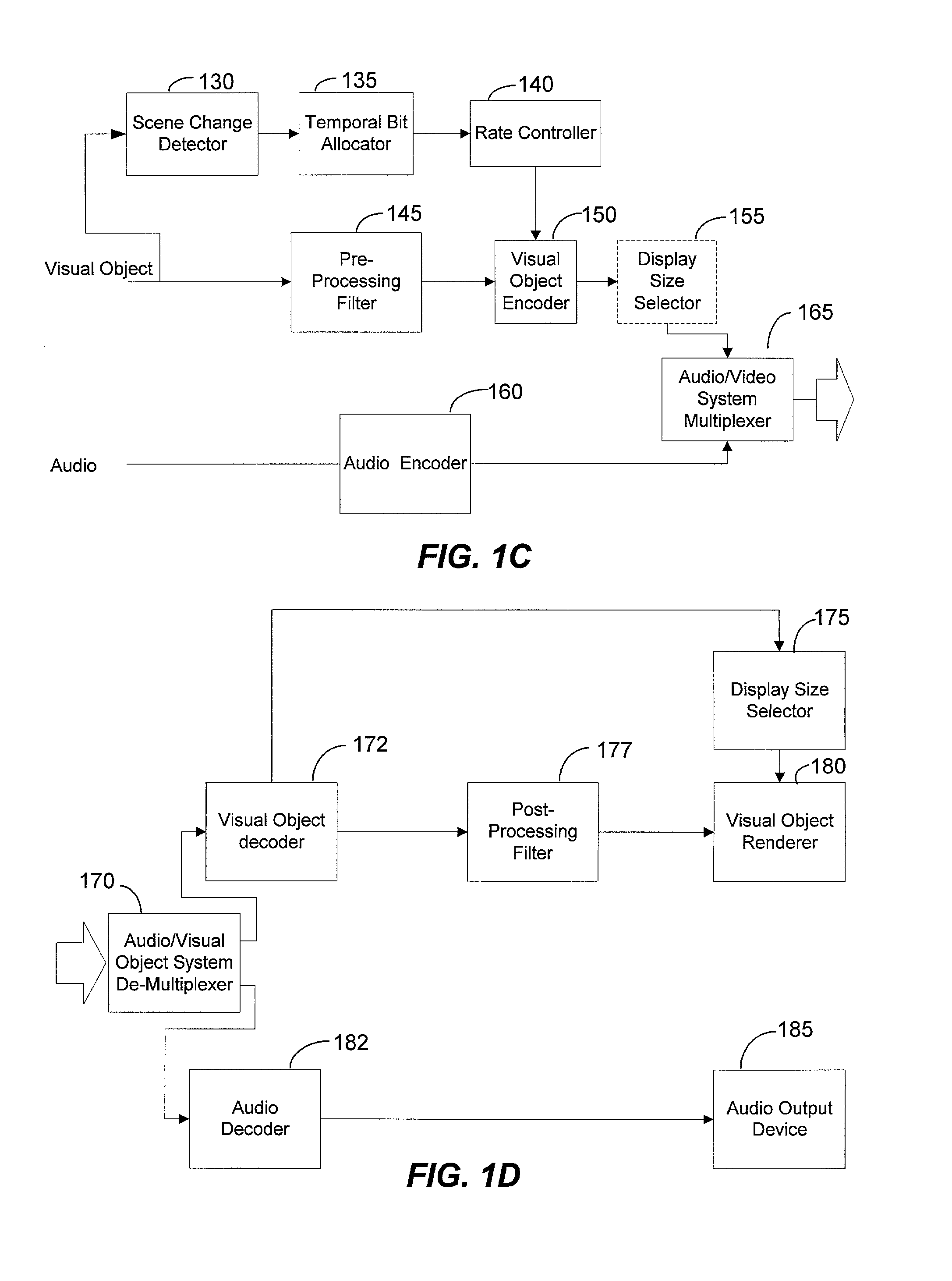
[0040] The present invention can determine the maximum size to display a visual object received from a computer network to a computer screen such that image degradations due to compression or transmission defects are the least noticeable. The visual object can comprise one of video, a graphical image, and other like visual objects. In one exemplary embodiment, a coding difficulty value can be calculated during compression of a visual object in a conventional format, such as Moving Picture Experts Group (MPEG) format, for computer network transmission. According to another aspect of the present invention, a coding difficulty value can be calculated from a received coded or compressed visual object that was transmitted over a computer network. An optimum display size can be calculated by mapping the harmonic average of the PSNR and the visual object transmission rate and determining the zone in which the coordinates are located.

[0041] Illustrative Operating Environment

[0042] The prese...


PUM


Abstract

A method and system can automatically select the optimal size of a visual object that can be displayed on an display device. For example, the present invention can determine the best or optimum size to display a visual object received from a computer network to a computer screen such that image degradations due to compression or transmission defects are less noticeable or perceivable. Typically, the best or optimum size to display a visual object can comprise a size that is also the maximum in which the visual object can be displayed without any degradations or defects.

Description

PRIORITY AND RELATED APPLICATIONS[0001] The present application claims priority to provisional patent application entitled, "VIDEO PROCESSING METHOD WITH GENERAL AND SPECIFIC APPLICATIONS," filed on Jul. 11, 2000 and assigned U.S. application Ser. No. 60 / 217,301. The present application is also related to non-provisional application entitled, "ADAPTIVE EDGE DETECTION AND ENHANCEMENT FOR IMAGE PROCESSING," (attorney docket number 07816-105003) filed on Jul. 11, 2001 and assigned U.S. application Ser. No. ______; and non-provisional application entitled, "VIDEO COMPRESSION USING ADAPTIVE SELECTION OF GROUPS OF FRAMES, ADAPTIVE BIT ALLOCATION, AND ADAPTIVE REPLENISHMENT," (attorney docket number 07816-105004) filed on Jul. 11, 2001 and assigned U.S. application Ser. No.______.[0002] The present invention relates generally to video processing techniques. More particularly, the present invention relates to a method and system for calculating an optimum display size for a visual object.BA...

Claims


Application Information

Patent Timeline
Patent Type & Authority Applications(United States)
IPC IPC(8): G06T3/40G06T5/00G06T9/00H04N5/14H04N7/26
CPCG06T3/403G06T3/4092G06T7/0083G06T9/00G06T9/007G06T2207/10016H04N19/527H04N5/147H04N19/172H04N19/107H04N19/114H04N19/137H04N19/152G06T2207/20192G06T7/12
Inventor JAYANT, NUGGEHALLY S.JANG, SEONG H.YOON, JANGHYUN
Owner ARRIS GROUP
Why Eureka
Try Eureka