Multifunction display design tool

a multi-functional display and design tool technology, applied in the field of data processing system interactions, can solve problems such as lack of human teller presen

Inactive Publication Date: 2002-03-28
UNITED STATES OF AMERICA THE AS REPRESENTED BY THE SEC OF THE ARMY
View PDF11 Cites 13 Cited by
  • Summary
  • Abstract
  • Description
  • Claims
  • Application Information

AI Technical Summary

Benefits of technology

0036] FIG. 13 shows the MFD Set Frame Information window allowing th...

Problems solved by technology

However, unlike the previous example, there is no human teller present to assist the human engaging in the banking transaction.
Mapping the information hierarchy to the one or more buttons on the one or more displayed pages in a fashion that decreases the likelihood of confusion is generally considered to be an extremely challenging task within the art.
However, insof...

Method used


Image

  • Multifunction display design tool
  • Multifunction display design tool
  • Multifunction display design tool

Examples


Embodiment Construction

)

[0055] The following sets forth a detailed description for carrying out the devices and / or processes described herein. The description is intended to be illustrative and should not be taken to be limiting.

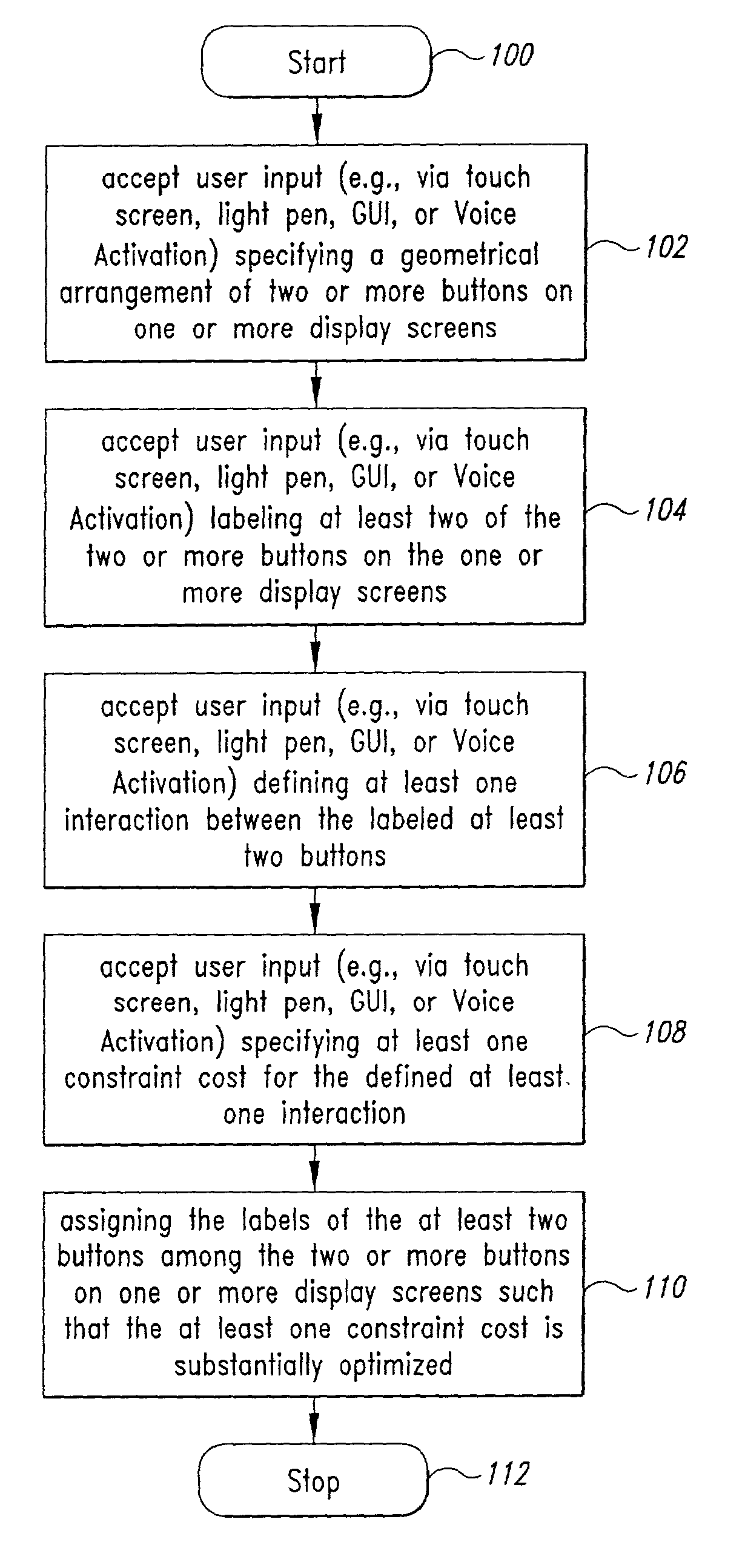
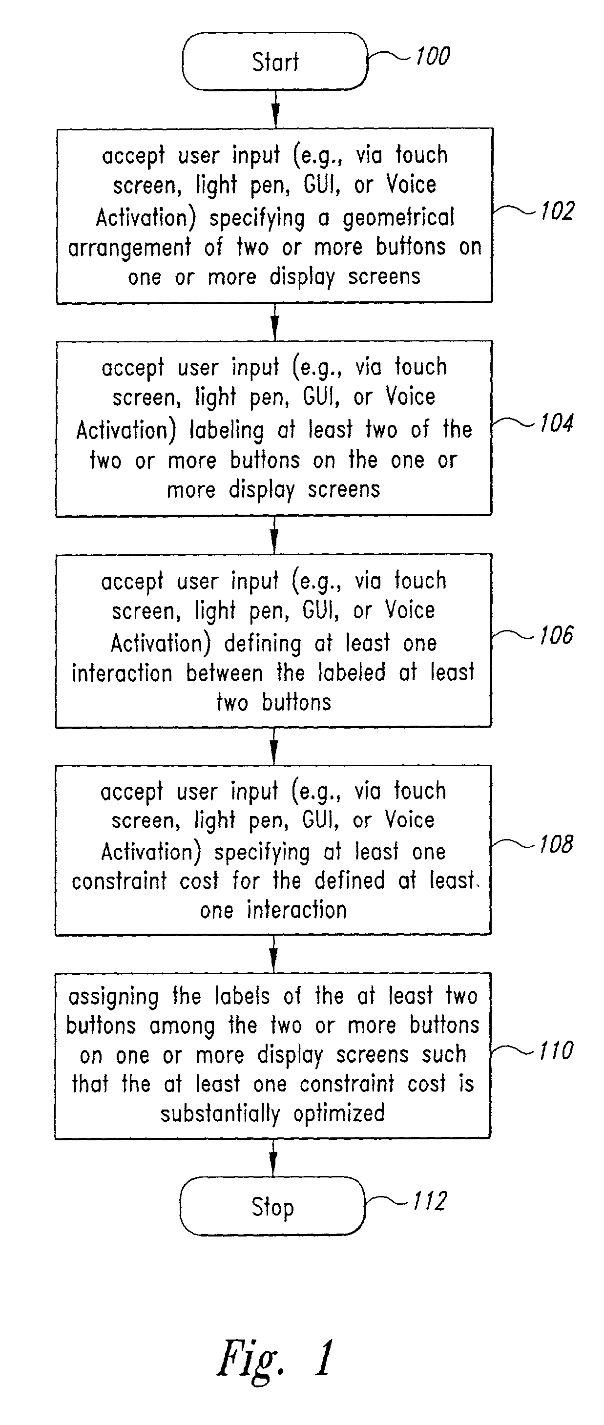
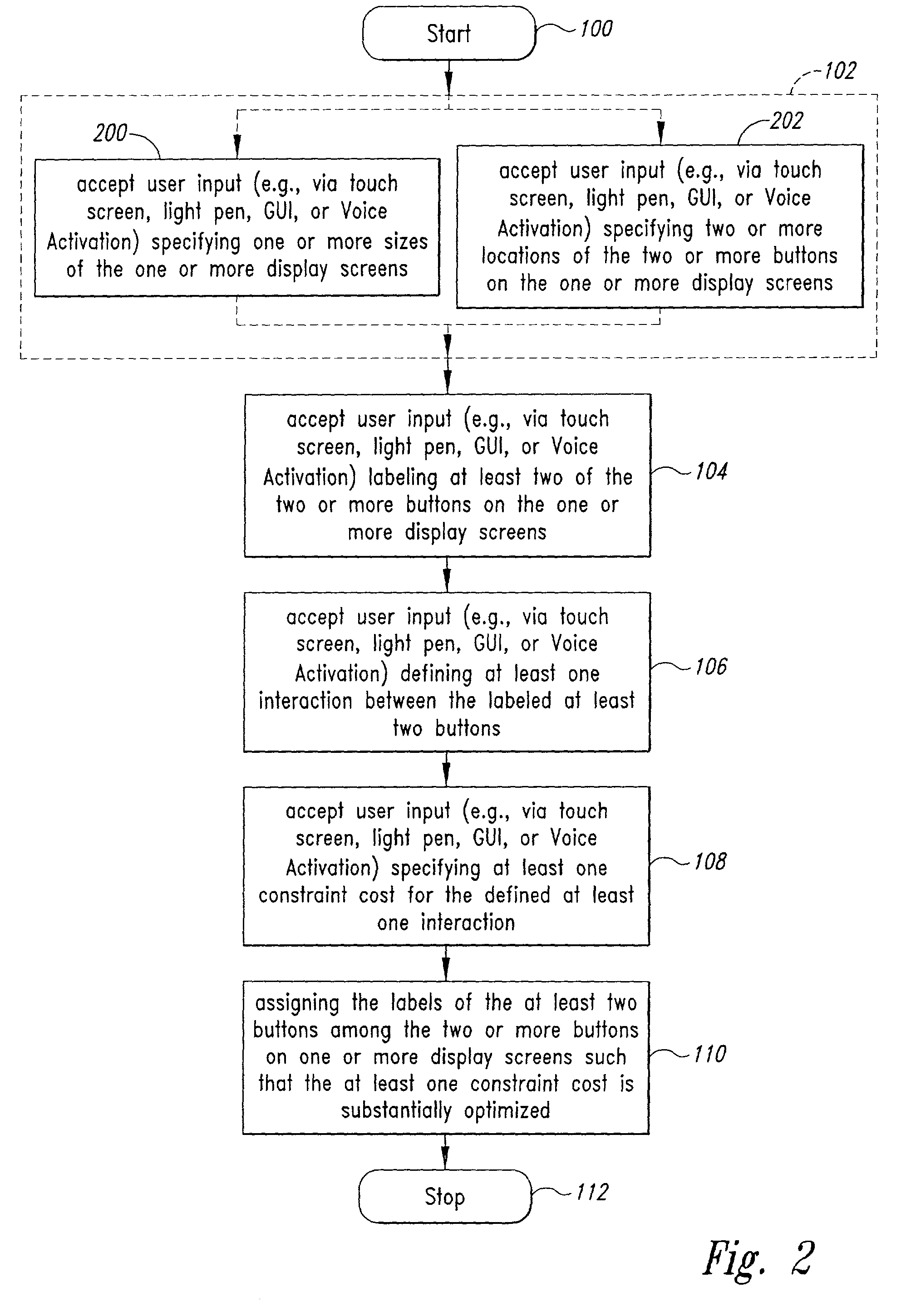
[0056] As noted in the description of the related art, the inventors have discovered that the design skills of the human designer can be enhanced by devices and processes devised by the inventors which allow for automated assignment of button labels across one or more displayed pages in response to input quantitatively specifying design constraints and tradeoffs. In making the foregoing-noted discovery, the inventors studied expert human MFD designers and discovered that the expert human MFD designers studied tended to rely on a balancing of a multitude of general guidelines. The inventors found that the general guidelines were in general heuristic (human-psychological) guidelines which could not, in general, be adapted to an automated approach. As a result of such research the in...


PUM


Abstract

A method that includes but is not limited to accepting user input specifying a geometrical arrangement of two or more buttons on one or more displayed pages; accepting user input labeling at least two of the two or more buttons on the one or more displayed pages; accepting user input defining at least one interaction between the labeled at least two buttons; accepting user input specifying at least one constraint cost for the defined at least one interaction; and assigning the labels of the at least two buttons among the two or more buttons on one or more displayed pages such that the at least one constraint cost is substantially optimized. In addition to the foregoing, other method embodiments are described in the claims, drawings, and text forming a part of the present application. In one or more various embodiments, related systems include but are not limited to circuitry and/or programming for effecting the foregoing-described method embodiments; the circuitry and/or programming can be virtually any combination of hardware, software, and/or firmware configured to effect the foregoing-described method embodiments depending upon the design choices of the system designer.

Description

CROSS REFERENCE(S) TO RELATED APPLICATIONS[0001] This patent application hereby incorporates by reference in its entirety pending Provisional Patent Application No. 60 / 223,867, filed Aug. 8, 2000, naming Gregory S. Francis, Clarence E. Rash, and Matthew J. Reardon as inventors; furthermore, this patent application also claims the benefit of the foregoing-referenced pending provisional patent application No. 60 / 223,867 under the auspices of 35 U.S.C. .sctn. 119(e).[0002] 1. Field of the Invention[0003] The devices and processes described herein relate, in general, to data processing system interactions.[0004] 2. Description of the Related Art[0005] Data processing systems are systems that manipulate, process, and store data. Personal computer systems, and their associated subsystems, constitute well-known examples of data processing systems.[0006] Data processing systems often provide assistance to humans. Examples of such assistance are automated co-pilots which assist human pilots ...

Claims


Application Information

Patent Timeline
IPC IPC(8): G06F9/44
CPCG06F9/4443G06F9/451
Inventor FRANCIS, GREGORY S.RASH, CLARENCE E.REARDON, MATTHEW J.
Owner UNITED STATES OF AMERICA THE AS REPRESENTED BY THE SEC OF THE ARMY
Why Eureka
Try Eureka