
Electrical junction box

a junction box and electric technology, applied in the direction of electric/fluid circuit, printed circuit, transportation and packaging, etc., can solve the problems of high cost, inaccurate orientation of busbar terminals on the distribution board, and high cost of molding dies for the lower cover

Inactive Publication Date: 2002-05-23
YAZAKI CORP
View PDF1 Cites 25 Cited by
  • Summary
  • Abstract
  • Description
  • Claims
  • Application Information

AI Technical Summary

Problems solved by technology

Generally, the busbar terminals attached on the distributing board are not accurately oriented with variations in orientation thereof.
The conventional lower cover 10 of such construction is not suitable for size minimization of the electrical junction box X. A molding die for the lower cover 10 tends to be expensive since the molding die may have a larger size so as to form the extended portion of the through-hole portion 8c.

Method used


Image

  • Electrical junction box
  • Electrical junction box
  • Electrical junction box

Examples


Embodiment Construction

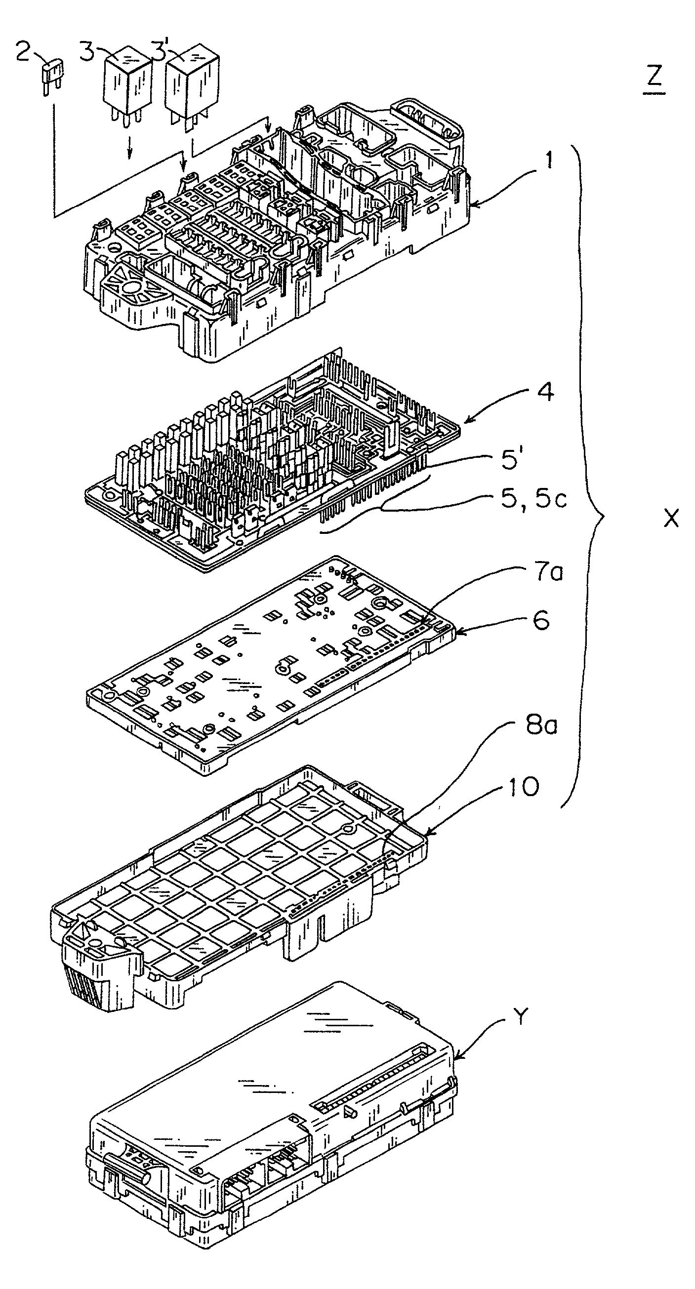
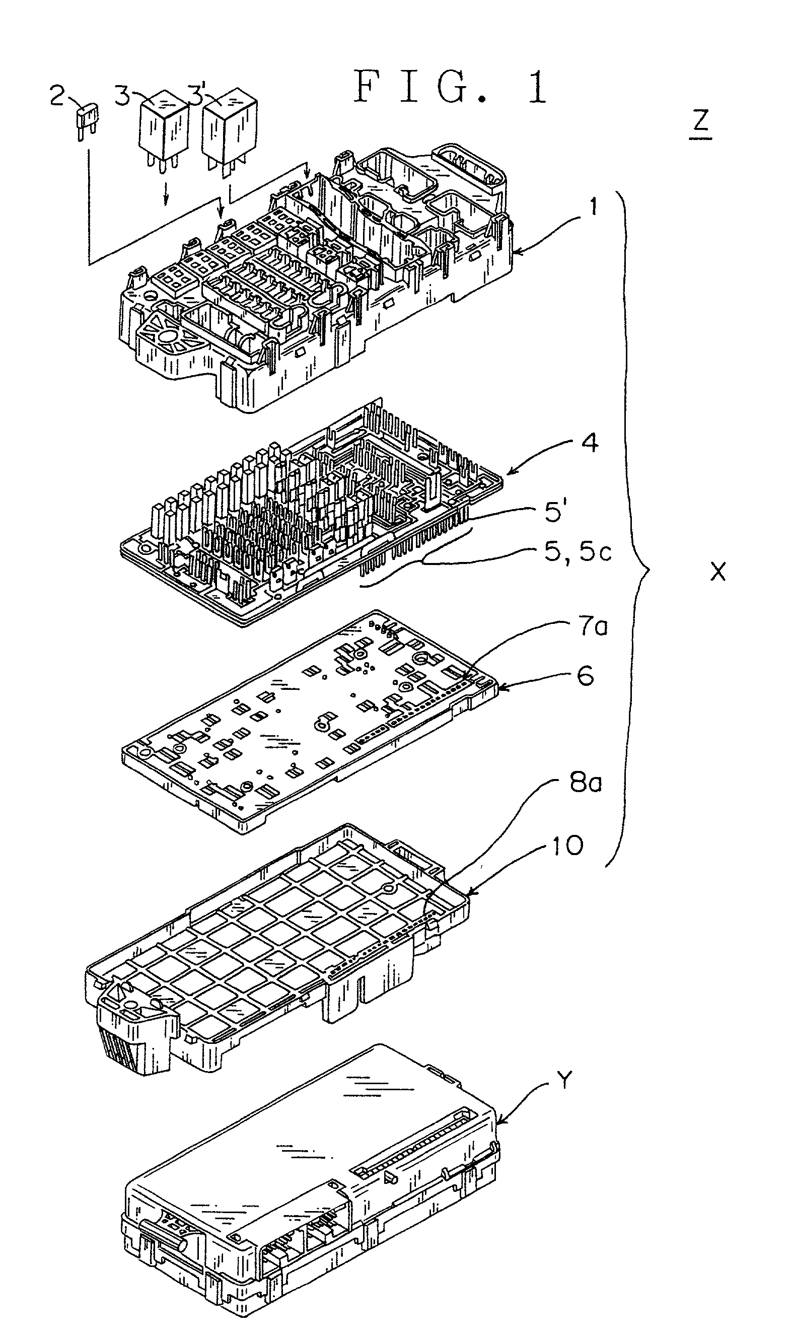
[0055] Referring to FIGS. 1 to 8, an embodiment of the electrical junction box according to the present invention will be discussed. The same components as those of the aforementioned conventional electrical junction box have the same reference numerals as the conventional art and will not be discussed again.

[0056] Now, the electrical junction boxes X, Y, and Z will be discussed. The electrical junction box X comprises an upper cover 1, a distributing board 4, a wiring sheet 6, and a lower cover 10. A first box is the electrical junction box X. A second box is the electrical junction box Y which is combined with the first electrical junction box X. The electrical junction box Z is a box defined by combining the first electrical junction box X with the second electrical junction box Y.

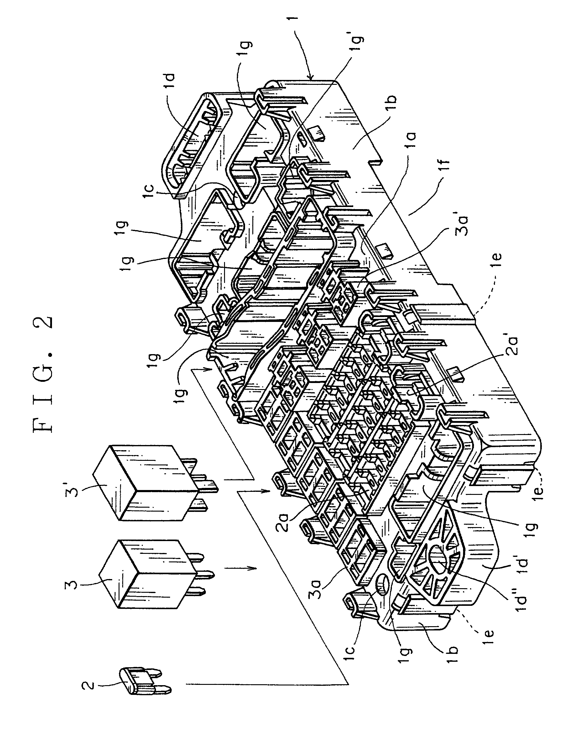
[0057] As illustrated in FIGS. 1 and 2, the upper cover 1 has fuses 2 and relays 3, 3' in an upper side thereof. As illustrated in FIG. 4, the wiring sheet 6 has routing conductors 9 in a lower side the...


PUM


Abstract

The electrical junction box X includes an upper cover 1, a distributing board 4 fitted with a busbar 5, a wiring sheet 6, and the lower cover 10. The lower cover 10 is formed with a through-hole 8a which is inserted by a terminal 5' of the busbar 5. The wiring sheet 6 is provided with a through-hole 7a through which the terminal 5' of the busbar 5 is inserted. This allows a smaller assembling tolerance between the terminal 5' of the busbar 5 and the through-hole 8a in combination of the wiring sheet 6b attached to the distributing board 4 with the lower cover 10.

Description

[0001] 1. Field of the Invention[0002] The present invention relates to an electrical junction box such as a junction box and a relay box which are used for electrical wiring, for example, of an automotive vehicle. The present invention relates particularly to an electrical junction box having a construction which allows an easy combining work of a lower cover, a wiring sheet, etc. thereof.[0003] 2. Related Art[0004] Referring to FIG. 9, a conventional junction box X or a conventional electrical junction box such as a relay box and components including a distributing board 4 of the box will be briefly discussed hereinafter.[0005] FIG. 9 is an exploded perspective view of the conventional electrical junction box X which comprises an upper cover 1, a distributing board 4, a wiring sheet 6, routing conductors 9 and a lower cover 10. The electrical junction box X has a junction box main body consisting of the upper cover land the lower cover 10 which are made of a synthetic resin materi...

Claims


Application Information

Patent Timeline
Patent Type & Authority Applications(United States)
IPC IPC(8): B60R16/02H01R9/22H02G3/08H02G3/16H05K7/02
CPCH01R9/226H05K7/026H02G3/086
Inventor SATO, KUMIKO
Owner YAZAKI CORP
Learn More