Utility monitoring and control systems

a technology of monitoring and control system and control system, applied in the direction of process and machine control, digital computer details, instruments, etc., can solve problems such as uncommanded occurrence, and achieve the effect of facilitating/permitting communication

Inactive Publication Date: 2002-06-27
INTERNET ENERGY SYST INC IES
View PDF37 Cites 89 Cited by
  • Summary
  • Abstract
  • Description
  • Claims
  • Application Information

AI Technical Summary

Benefits of technology

0181] Important advantages follow from establishment of a communication channel by the communication means 14 of a DC&CT unit 11 to a CCT&DG unit 12. If CCT&DG unit 12 is outside a physical network 40 of which the DC&CT unit 11 is part, the CCT&DG unit 12 can send one or more messages to the DC&CT unit 11 without having to initiate the communications. Thus, when such a physical network 40 is protected by a firewall, such as firewall 48, initiation of communication by a communication means 14 located ins...

Problems solved by technology

However, in the present aspect, during at least a portion of these communications, transmission of consumption data through the communications means to the at l...

Method used


Image

  • Utility monitoring and control systems
  • Utility monitoring and control systems
  • Utility monitoring and control systems

Examples


Embodiment Construction

[0051] The inventions disclosed herein include a number of improvements upon, alternative embodiments and preferred embodiments, including best modes, of the method and apparatus aspects of the invention described above under Summary of the Inventions. Among these improvements and preferred embodiments are methods, which may be combined with the first and second method modes singly or in any combination, wherein:

[0052] a plurality of said utility demand control units and at least one centralized command transmission unit are provided.

[0053] a plurality of said utility consumption tracking units and at least one centralized data gathering unit are provided.

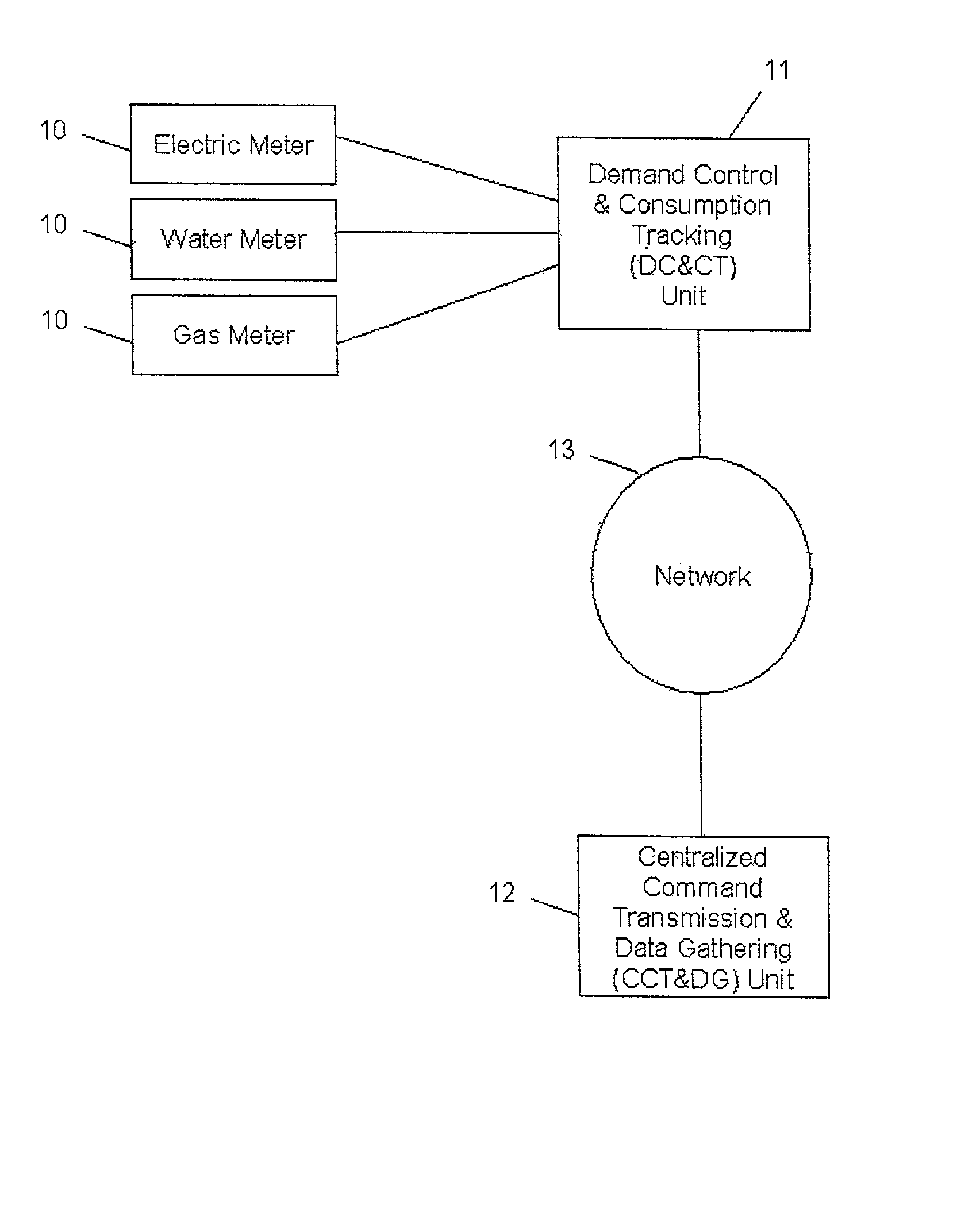
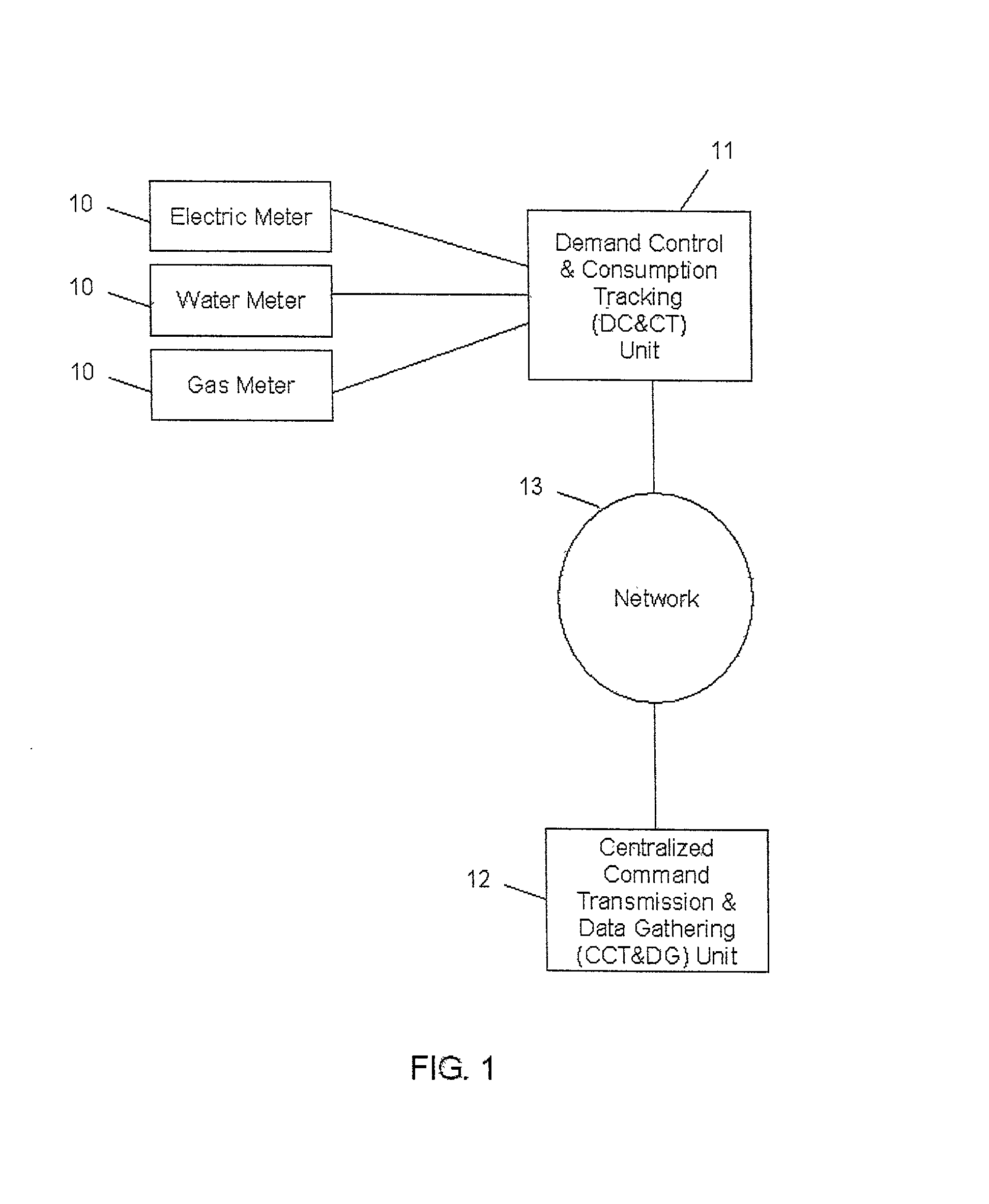
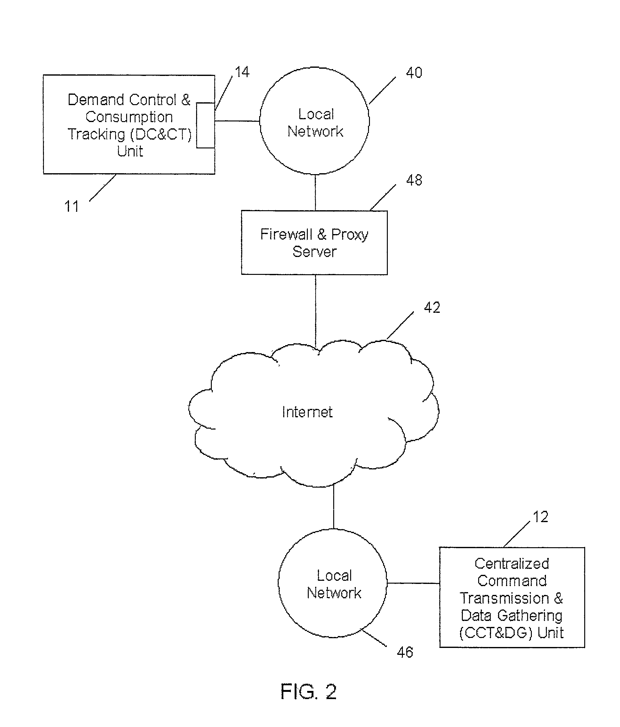
[0054] a plurality of said utility demand control and consumption tracking units and at least one centralized command transmission and data gathering unit are provided.

[0055] there are utility demand control and consumption tracking units that comprise separate but interconnected components that respectively perform demand control ...


PUM


Abstract

A method of communication useful in remote utility demand control systems, automated utility data gathering systems and combined utility demand control and data systems is disclosed. Also disclosed is an utility remote demand control and/or automated data gathering system. Different methods of communications between a utility demand control and consumption tracking unit, which is connected to different utility consuming devices, on the one hand, and a centralized command transmission and data gathering unit, on the other hand, are described. The communication between these units includes at least one computer information network.

Description

CROSS-REFERENCES TO RELATED APPLICATION[0001] This application claims the benefit under 35 U.S.C. .sctn.120 to the filing dates of U.S. Provisional Application, Serial No. 60 / 211,468, filed Jun. 15, 2000. This application claims the benefit under 35 U.S.C. .sctn.120 to the filing dates of and is a continuing application of (1) U.S. Application "UTILITY MONITORING AND CONTROL SYSTEMS," filed Jun. 15, 2001, Ser. No. 09 / 881,205 and (2) U.S. Application "UTILITY MONITORING AND CONTROL SYSTEMS," filed Jun. 18, 2001, Ser. No. 09 / 882,378.INCORPORATION BY REFERENCE[0002] This application incorporates by reference the entire disclosures of U.S. Provisional Application, Serial No. 60 / 221,468, filed Jun. 15, 2000 and U.S. Application "UTILITY MONITORING AND CONTROL SYSTEMS," filed Jun. 15, 2001, Ser. No. 09 / 881,205 and U.S. Application "UTILITY MONITORING AND CONTROL SYSTEMS," filed Jun. 18, 2001, Ser. No. 09 / 882,378.[0003] The invention relates to the monitoring and / or control of demand for a...

Claims


Application Information

Patent Timeline
IPC IPC(8): G01D4/00G01F1/00G01F7/00G05D3/12G05D5/00G05D9/00G05D11/00G05D17/00G06F15/173
CPCG01D4/004Y02B90/242Y04S20/42Y04S20/322Y02B90/246G01D2204/45Y02B90/20Y04S20/30
Inventor ENGA, DAVID A.ENGA, JAMES C.ENGA, JAMES N.FERRATT, JILL C.HOLEC, JULIE A.VIANA, EVANDRO V.LAVAL, DAVID K.
Owner INTERNET ENERGY SYST INC IES
Why Eureka
Try Eureka