Method for determining a value relating to compressing rate of a baler

a baler and compressing rate technology, applied in the field of sensing the capacity, can solve the problems of system overload, limited to integer values, and reduced efficiency

Inactive Publication Date: 2002-08-15
BLUE LEAF I P INC
View PDF0 Cites 40 Cited by
  • Summary
  • Abstract
  • Description
  • Claims
  • Application Information

AI Technical Summary

Problems solved by technology

One problem with the indication system described above is that it is limited to integer values.
However, at some point the system is overloaded--usually resulting in the breaking of specially dimensioned shear bolts which are provided to prevent serious damage to the working components of the baler.
However, replacing a shear bolt takes time and results in a lower efficiency.
However, operating of the clutch stops operation of the relevant element so that efficiency must inevitably fall.

Method used


Image

  • Method for determining a value relating to compressing rate of a baler
  • Method for determining a value relating to compressing rate of a baler
  • Method for determining a value relating to compressing rate of a baler

Examples


Embodiment Construction

[0030] The present invention will be described with reference to certain embodiments and to certain drawings but the present invention is not limited thereto but only by the claims. For instance, the present invention will mainly be described with reference to a pre-compression chamber or duct located underneath the baling chamber but the present invention is not limited thereto but may be advantageously used with a pre-compression or collecting chamber above the baling chamber as is known, for instance, from U.S. Pat. No. 4,193,251 (but without the novel features of the present invention).

[0031] The terms "front", "rear", "forward", "rearward", "left", "right", "upward", and "downward" as used throughout this description are determined with respect to the normal direction of travel of the baler in operation and in its normal orientation unless otherwise stated. However they are not to be construed as limiting terms.

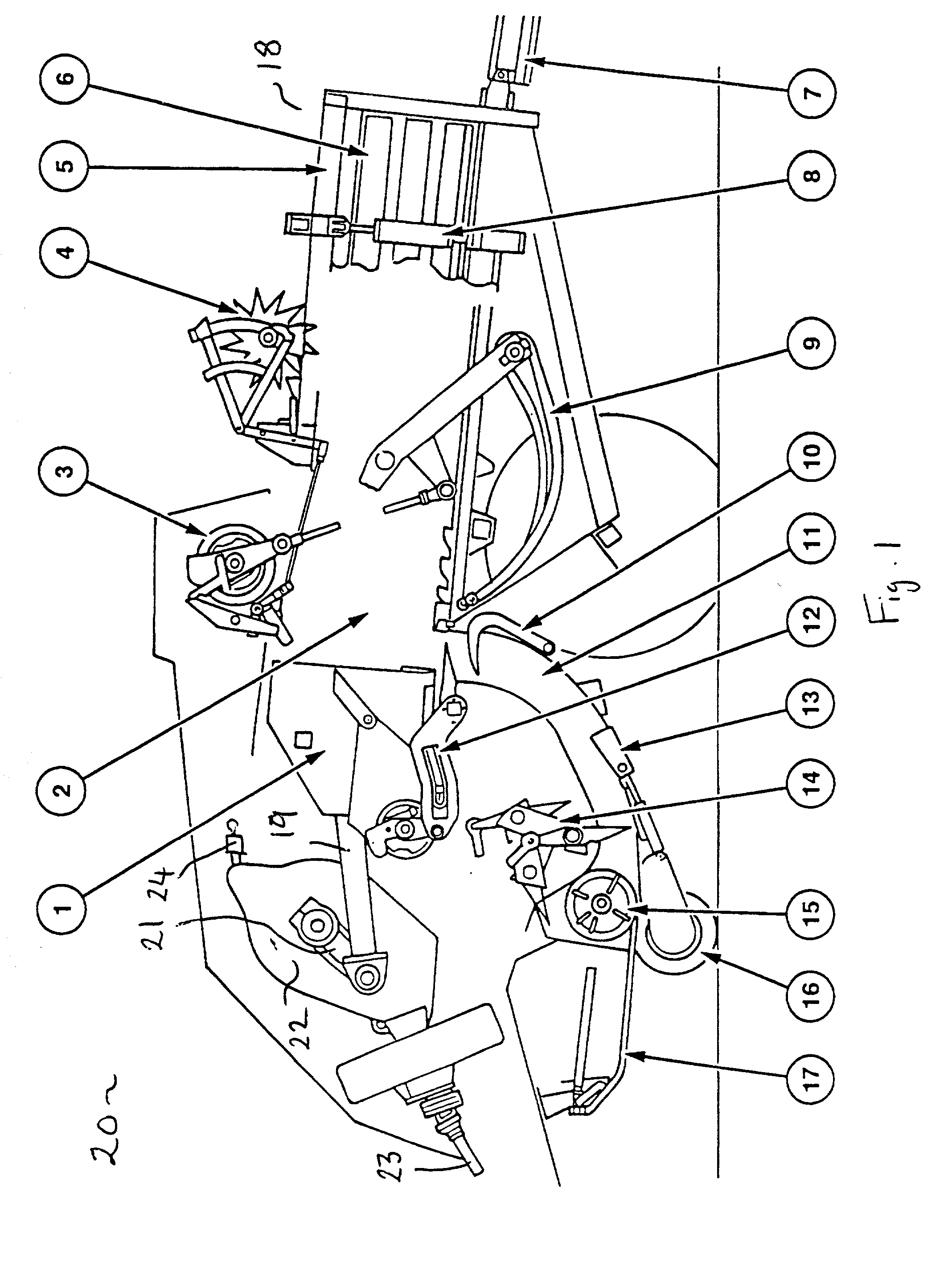
[0032] FIG. 1 shows an agricultural baler 20 comprising a frame or ...


PUM


Abstract

A baler is described which has a collection chamber or duct and a baling chamber. Crop material enters the duct until a pre-determined level has been reached at which time a stuffer transfers the pre-compressed crop to the baling chamber. A control system is provided for calculating the ratio between the amount of crop material which should be formed into bales under optimal conditions and the rate of flow of crop material entering the duct. This ratio can be displayed and used to control the speed of the towing vehicle. The present invention uses the duct as a kind of measuring cylinder to determine the rate at which crop material is entering the baler.

Description

BACKGROUND OF INVENTION[0001] 1. Field of Art[0002] The present invention relates generally to an apparatus and a method for optimizing the operation of an agricultural baler, and more particularly to sensing the capacity at which the baler is operating. In particular the baler is adapted to determine the ratio between an optimum rate of production of packages of crop material formed in the baling chamber of the baler and the actual flow rate of material entering the baler from the field. The present invention also includes a control system and method for determining the capacity at which the baler is operating, for example for determining the ratio between an optimum rate of production of packages of crop material formed in the baling chamber of the baler and the flow rate of material entering the baler from the field. The invention has particular application to optimizing the normal operation of the baler under conditions when charges of crop material fed into the baler are varyin...

Claims


Application Information

Patent Timeline
Patent Type & Authority Applications(United States)
IPC IPC(8): A01F15/08
CPCA01F15/0825
Inventor LEUPE, DIRK G. C.LIPPENS, CHRISTIAAN A. C.
Owner BLUE LEAF I P INC
Why Eureka
Try Eureka