Electromagnetic actuator and shutter device for camera

Inactive Publication Date: 2002-08-22
NIDEC COPAL CORPORATION
View PDF0 Cites 8 Cited by
  • Summary
  • Abstract
  • Description
  • Claims
  • Application Information

AI Technical Summary

Benefits of technology

0031] According to this structure, when the rotor is located at the initial position in the current-stopped state, a strong magnetic attraction force (rotational urging force) acts between the rotor projection and the auxiliary magnetic pole piece and between the second narrow facing surface and the first outer circumferential surface, by appropriately selecting the positions where the first narrow facing surface, the second narrow facing surface, the third narrow facing surface, etc., are disposed, and therefore the rotor is infallibly maintained at the initial position. On the other hand, in the current-running state, a strong repulsion force resulting from the fact that the same magnetic pole as a magnetic pole with which the rotor projection is magnetized

Problems solved by technology

However, since this structure has a disadvantage in the fact that a magnetic attraction force by which the rotor is maintained at an initial position (resting position) is weak in a current-stopped state in which an electric current is not passed through the coil, a technique is employed in which, for example, the relationship between the pair of magnetic pole parts and the magnetization angle of the rotor is changed, or a magnetic gap between the outer circumferential surface of the rotor and the magnetic pole parts is narrowed, in order to strengthen the magnetic attraction force and raise the maintaining force.
In order to raise the maintaining force according to techniques like the

Method used


Image

  • Electromagnetic actuator and shutter device for camera
  • Electromagnetic actuator and shutter device for camera
  • Electromagnetic actuator and shutter device for camera

Examples


Example

[0078] Embodiments of the present invention will be hereinafter described with reference to the attached drawings.

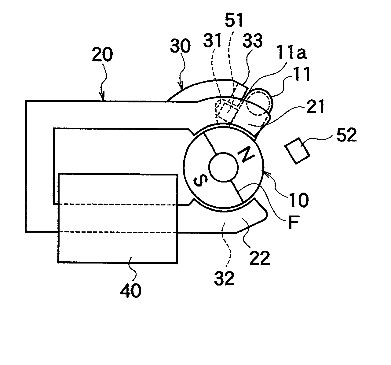
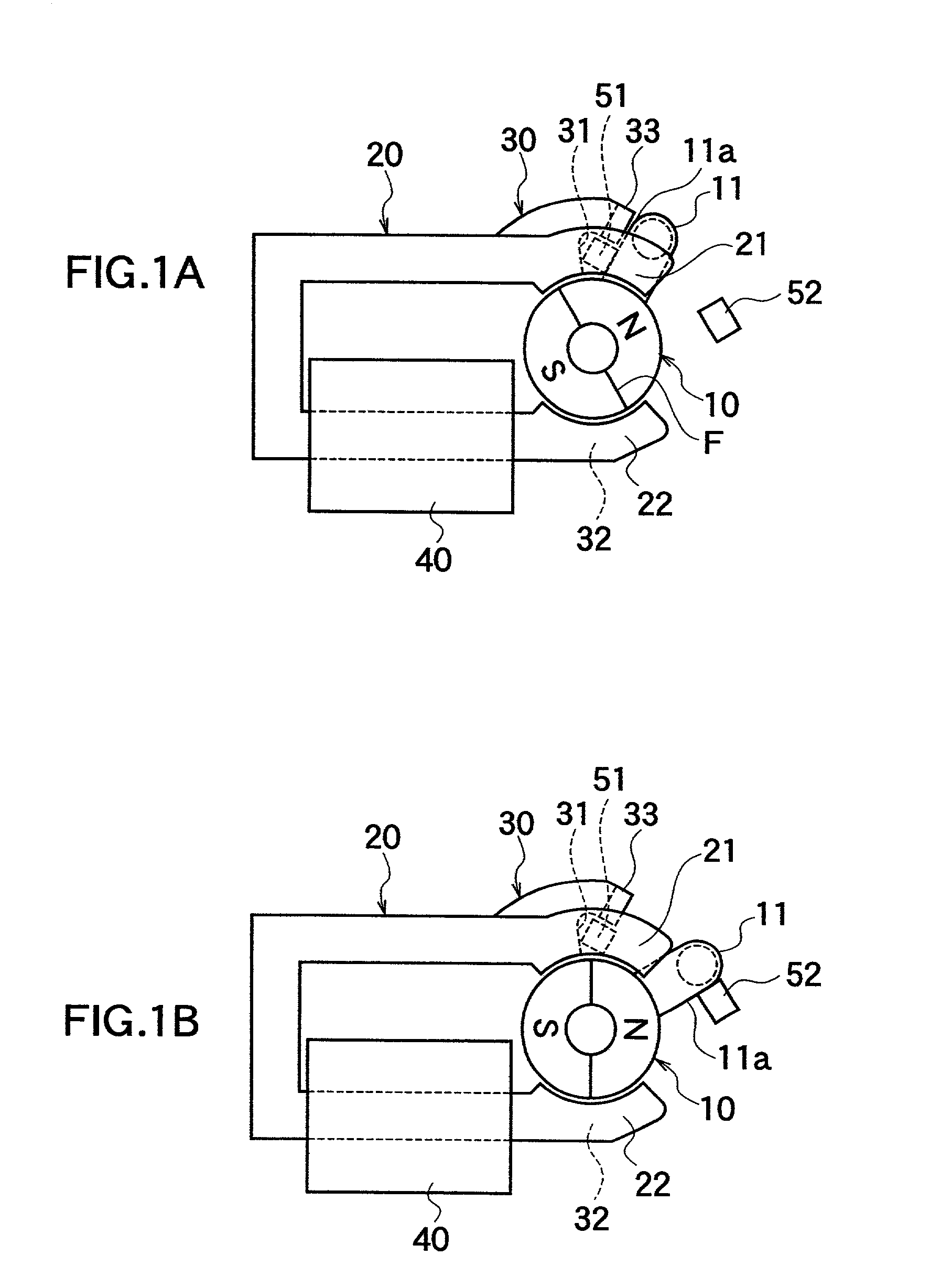
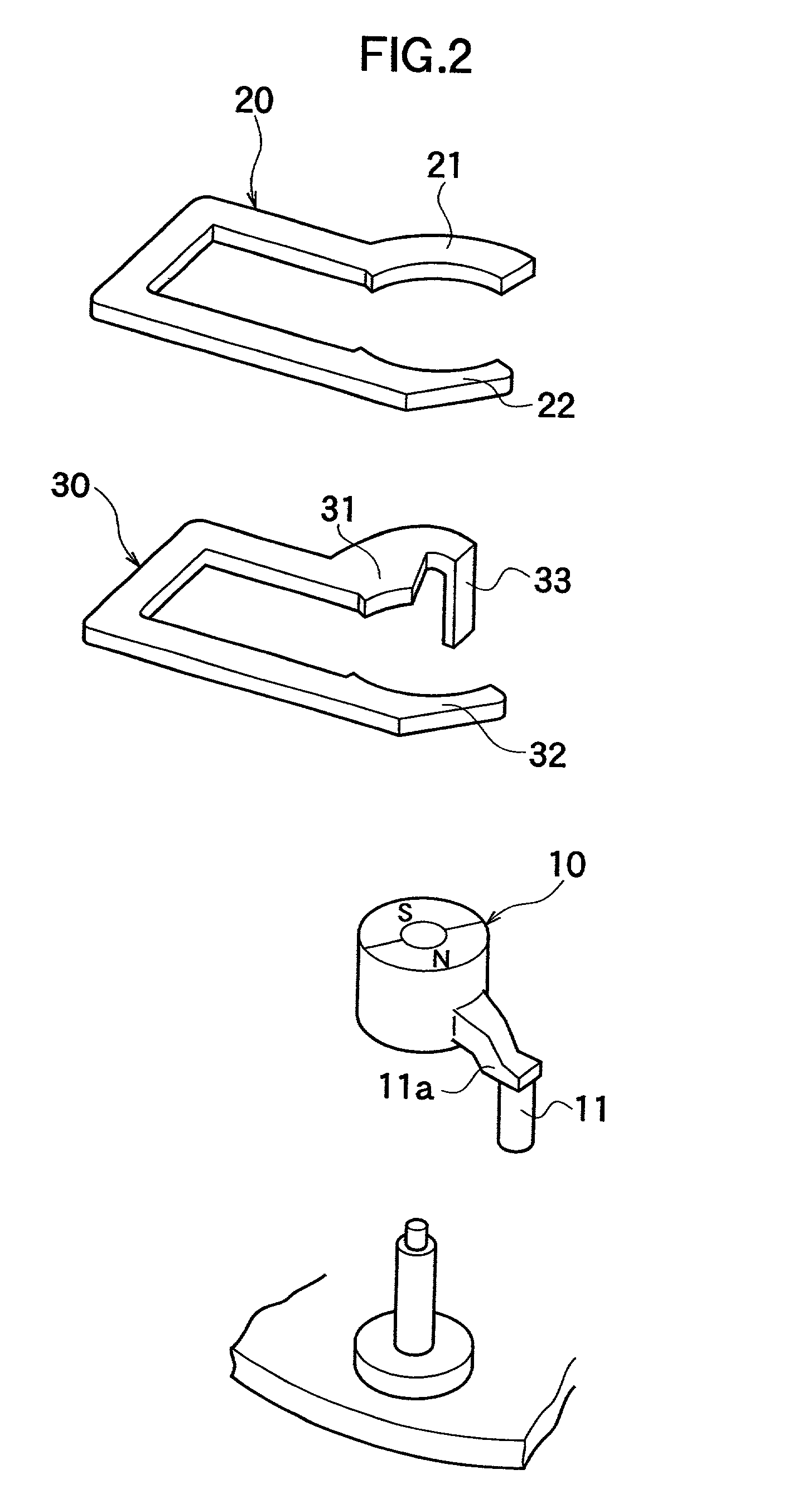
[0079] FIG. 1A, FIG. 1B, FIG. 2, and FIGS. 3A through 3E show one embodiment of the electromagnetic actuator according to the first aspect of the present invention. As shown in FIGS. 1A, 1B, and 2, the electromagnetic actuator according to this embodiment is made up of a rotor 10 magnetized with different polarities, i.e., with the N and S poles with a boundary plane F passing through a rotational shaft therebetween, first magnetic pole parts 21, 31 and second magnetic pole parts 22, 32 disposed to face the outer circumferential surface of the rotor 10, an auxiliary magnetic pole piece 33 disposed in the vicinity of the first magnetic pole part 31, a planar upper yoke 20 serving as a magnetic-path forming member that forms a magnetic path (magnetic circuit) by the connection between the first magnetic pole part 21 and the second magnetic pole part 22, a planar lower yoke...


PUM


Abstract

An electromagnetic actuator for driving the shutter of a camera includes a rotor (10) magnetized with the N and S poles, and first magnetic pole parts (21, 31) and second magnetic pole parts (22, 32) that are disposed to face the outer circumferential surface of the rotor (10) and generate mutually different magnetic poles when an electric current is applied to the coil (40), in which an output pin (11) of the rotor (10) is magnetized with one of the N and the S poles and forms a projection that projects outward in the radial direction, and, in the vicinity of the first magnetic pole part (31), an auxiliary magnetic pole piece (33) is provided that is disposed near the output pin (11) serving as a projection when the rotor (10) is located at an initial position and that generates the same magnetic pole as the first magnetic pole part (31) in a current-running state. Therefore, a maintaining force can be raised especially in a current-stopped state, and a driving force can be raised.

Description

[0001] The present invention relates to an electromagnetic actuator that generates a driving force by an electromagnetic force. More specifically, the present invention relates to an electromagnetic actuator that generates a rotational driving force by rotating by a predetermined angle range and that is employed for driving a camera shutter or the like, and the present invention relates to a camera shutter unit using this electromagnetic actuator.[0002] A conventional electromagnetic actuator is made up of, for example, a rotor magnetized with different polarities (the N pole and the S pole), a pair of arcuate magnetic pole parts disposed in such a way as to surround a part of the outer circumferential surface of the rotor, a yoke (magnetic-path forming member) that magnetically connects the magnetic pole parts to each other and forms a magnetic path (magnetic circuit), a magnetizing coil wrapped around a part of the yoke, etc.[0003] However, since this structure has a disadvantage ...

Claims


Application Information

Patent Timeline
IPC IPC(8): G03B9/08G03B9/36H02K26/00
CPCG03B9/08G03B9/36H02K26/00H02K21/185
Inventor WATANABE, NABUAKI
Owner NIDEC COPAL CORPORATION
Why Eureka
Try Eureka