Method for fabricating carbon nanotube array

a carbon nanotube and array technology, applied in the direction of aligned nanotubes, coatings, chemistry apparatus and processes, etc., can solve the problems of unsatisfactory alignment and/or configuration, low yield of all carbon nanotubes produced by the above method, and weakening the van der waals interaction between adjacent carbon nanotubes, etc., to achieve strong van der waals attractive force and clean surface

Inactive Publication Date: 2010-09-09
BEIJING FUNATE INNOVATION TECH +1
View PDF6 Cites 23 Cited by
  • Summary
  • Abstract
  • Description
  • Claims
  • Application Information

AI Technical Summary

Benefits of technology

[0008]In one embodiment, a method for fabricating a super-aligned carbon nanotube array with a clean smooth surface and strong van der Waals attractive force includes the following steps: providing a substrate having a flat and smooth surface; depositing a catalyst layer on the flat and smooth surface of the substrate, the rate of deposition of the catalyst layer being less than about 0.5 nanometers per second; and growing super-aligned carbon nanotubes directly from the catalyst layer by a chemical vapor deposition process. The chemical vapor deposition process includes the steps of: positioning the substrate with the catalyst layer thereon into a furnace; heating the furnace up to a predetermined temperature; supplying a reaction gas into the furnace; and growing a plurality of carbon nanotubes on the substrate such that the carbon nanotube array is formed on the substrate.

Problems solved by technology

However, all carbon nanotubes, which have been produced by these methods, tend to be low yield, costly to manufacture, and entangled in form.
However, a layer of amorphous carbon is deposited on an outer surface of the carbon nanotube array during the growth process, which weakens the van der Waals interaction between adjacent carbon nanotubes.
Therefore, the carbon nanotube array made by the above method typically has an unsatisfactory alignment and / or configuration.

Method used


Image

  • Method for fabricating carbon nanotube array
  • Method for fabricating carbon nanotube array
  • Method for fabricating carbon nanotube array

Examples


Embodiment Construction

[0016]The present method for fabricating a carbon nanotube array is further described below with reference to the drawings.

[0017]The preferred embodiment provide a method for fabricating a carbon nanotube array including the steps:

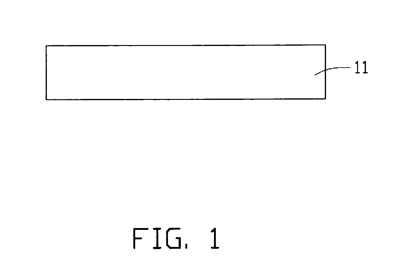
[0018]Step 1 provides a substrate with a flat and smooth surface (FIG. 1). The substrate 11 can, advantageously, be selected from the group consisting of a polished silicon wafer, a polished silicon dioxide wafer, and a polished quartz wafer. Preferably, a smoothness of the surface of the substrate 11 is less than 300 nm (nanometers) for facilitating a uniform formation of a catalyst layer directly on the substrate surface

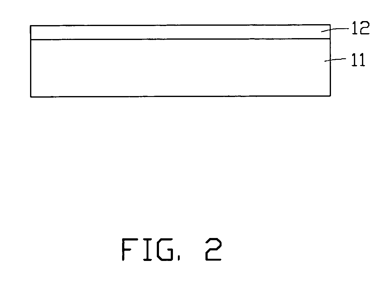
[0019]Step 2 includes the depositing of a catalyst layer on the flat and smooth surface of the substrate (FIG. 2). The catalyst layer 12 may be deposited on the surface of the substrate 11 by, e.g., electron beam evaporation or magnetron sputtering. The material of the catalyst layer 12 is, usefully, a transition metal such as iron, cobal...


PUM

PropertyMeasurementUnit
deposition rateaaaaaaaaaa
pressureaaaaaaaaaa
thicknessaaaaaaaaaa

Abstract

A method for fabricating a super-aligned carbon nanotube array includes the following steps: (1) providing a flat and smooth substrate (11); (2) depositing a catalyst layer (12) on the substrate at a rate of less than about 5 nm/s; (3) annealing the catalyst layer at atmosphere; (4) positioning the substrate with the catalyst layer into a furnace; (5) heating the furnace up to a predetermined temperature; and (6) supplying a reaction gas into the furnace, thereby growing a number of carbon nanotubes (22) on the substrate, via the catalyst layer, such that the carbon nanotube array is formed on the substrate.

Description

CROSS-REFERENCE TO RELATED APPLICATIONS[0001]This application is related to commonly-assigned, co-pending U.S. application Ser. No. 11 / 484,396 entitled, “METHOD FOR MANUFACTURING CARBON NANOTUBES”, filed Jul. 11, 2006. The disclosure of the above-identified application is incorporated herein by reference.BACKGROUND[0002]1. Field of the Invention[0003]The present invention relates to a method for fabricating a carbon nanotube array and, more particularly, to a method for fabricating a super-aligned carbon nanotube array.[0004]2. Discussion of Related Art[0005]Since being discovered in 1991, carbon nanotubes have been synthesized by numerous methods such as laser vaporization, arc discharge, pyrolysis chemical vapor deposition, plasma-enhanced chemical vapor deposition, and / or thermal chemical vapor deposition. However, all carbon nanotubes, which have been produced by these methods, tend to be low yield, costly to manufacture, and entangled in form.[0006]Fan et al. (Science, Vol. 283...

Claims


Application Information

Patent Timeline
Patent Type & Authority Applications(United States)
IPC IPC(8): C23C16/26
CPCB82Y30/00C01B2202/08C01B31/0233B82Y40/00C01B32/162
Inventor ZHANG, XIAO-BOJIANG, KAI-LIFAN, SHOU-SHAN
Owner BEIJING FUNATE INNOVATION TECH
Why Eureka
Try Eureka