
Laser radar based collision avoidance system for stationary or moving vehicles, automobiles, boats and aircraft

a collision avoidance system and radar technology, applied in the direction of braking system, using reradiation, instruments, etc., can solve the problem of being hit in the rear

Inactive Publication Date: 2002-08-29
STETTNER ROGER
View PDF16 Cites 115 Cited by
  • Summary
  • Abstract
  • Description
  • Claims
  • Application Information

AI Technical Summary

Benefits of technology

[0009] In the present invention electromagnetic signals reflected from objects surrounding a stationary or moving vehicle, are processed to develop a real-time, accurate, three-dimensional computational representation of the physical environment surrounding the moving vehicle. An on-board computer calculates the time of impact and warns the operator of the potential collision. Different embodiments of the invention present to the operator impact avoidance or damage minimization maneuvers. Still other embodiments of the present invention take over the controls and perform the selected maneuvers. Another embodiment of the present invention is able to penetrate obscurations such as fog and provide the same collision avoidance support to the operator with or without the obscuration present.

Problems solved by technology

However, this may put him in danger of being hit in the rear by a heavy vehicle that he has not seen in his rear view mirror.

Method used


Image

  • Laser radar based collision avoidance system for stationary or moving vehicles, automobiles, boats and aircraft
  • Laser radar based collision avoidance system for stationary or moving vehicles, automobiles, boats and aircraft
  • Laser radar based collision avoidance system for stationary or moving vehicles, automobiles, boats and aircraft

Examples


Embodiment Construction

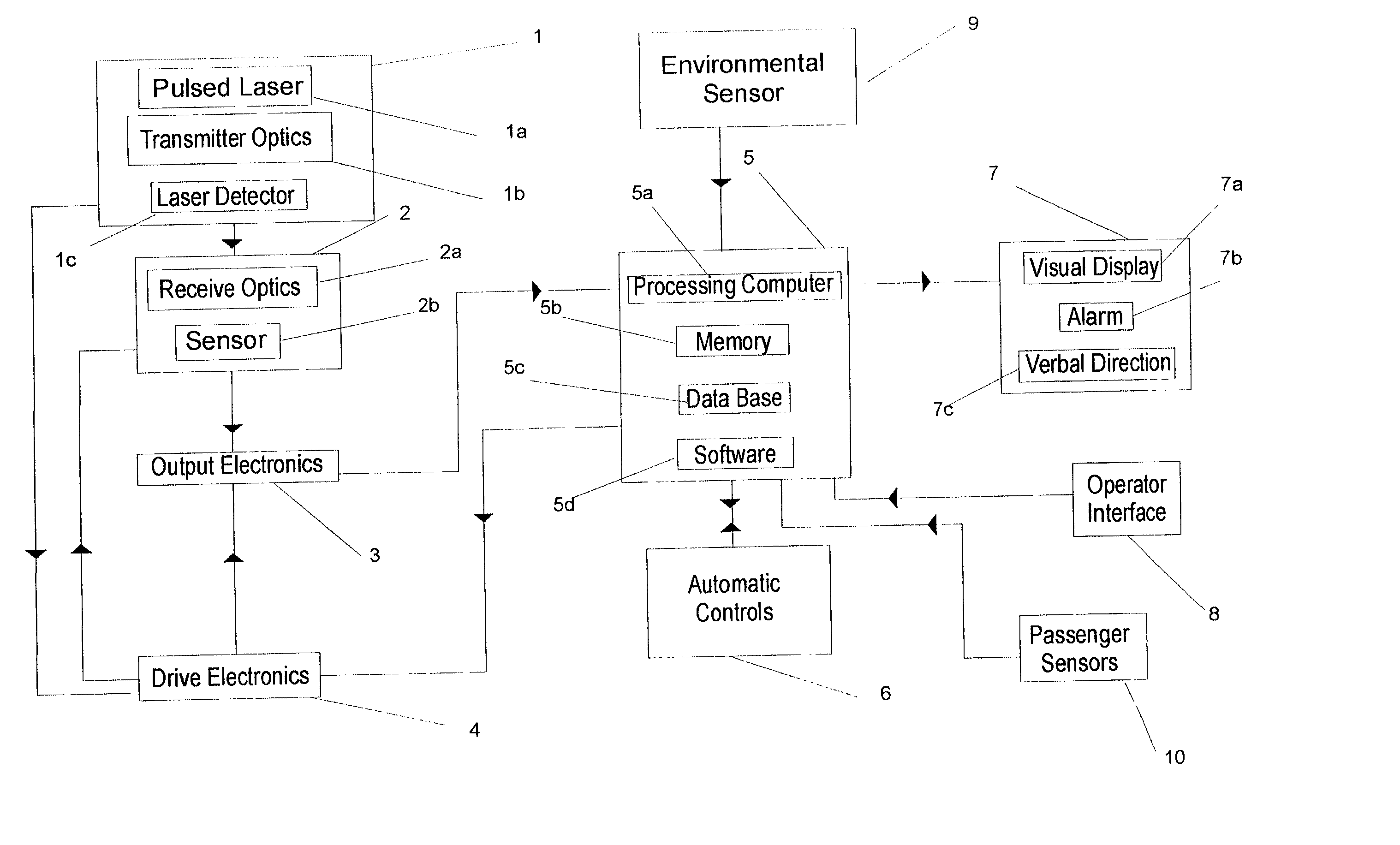
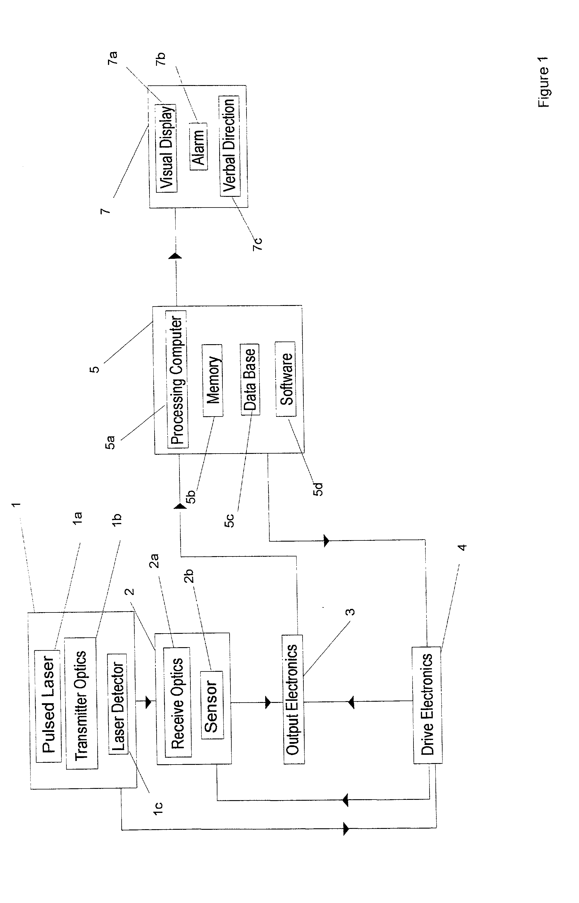
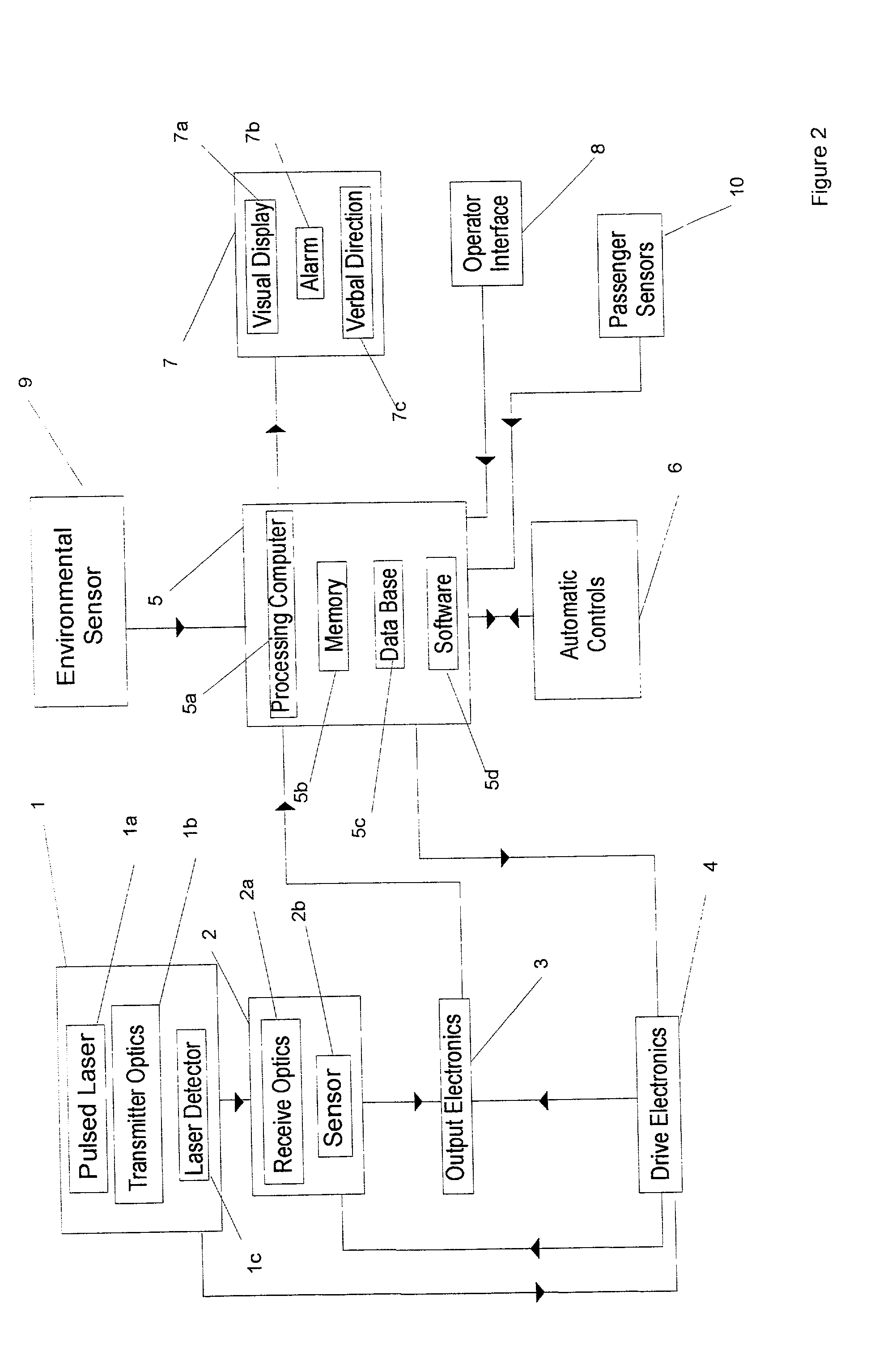
[0017] Two preferred embodiments of the present invention, the Ladar Based Collision Avoidance System (LBCOS) are depicted in FIGS. 1 and 2. LBCOS is designed to generate accurate 3-D representations of the objects, and their range, in all or a faction of the space surrounding a stationary or moving vehicle. LBCOS then processes these representations to determine collision likelihood with portions of the vehicle and the objects. The operator is alerted to a possible collision visually and / or verbally. The communication may include a suggested emergency maneuver. The visual communication with the operator may include a display of the surrounding objects on a screen with or without dynamic and range parameters such as velocity, acceleration and distance. The display may suggest a collision avoidance or minimum damage maneuver and monitor the maneuver in real time with continuous feedback to the operator. It is also possible that under predetermined circumstances LBCOS could take contr...


PUM


Abstract

A laser radar device for transmitting laser pulses, collecting the reflected data from surrounding objects, producing the three-dimensional time-dependent object representations and using these dynamic three-dimensional representations in avoiding collisions or minimizing damage resulting from collisions.

Description

[0001] This invention relates to an apparatus capable of developing three-dimensional range representations of the objects surrounding a stationary or moving vehicle, with or without the presence of obscuration, calculating the likelihood of collisions with these objects and warning the operator of these potential collisions. In particular, this invention relates to a laser radar device for transmitting laser pulses, collecting the reflected data from surrounding objects, producing the three-dimensional time dependent object representations and using these dynamic three-dimensional representations in avoiding collisions or minimizing damage resulting from collisions.[0002] Modern laser radar (ladar), by accurately detecting the time-of-return of reflected signals from surrounding objects, can not only rapidly construct an accurate 3-D image of these objects but the range to these objects as well. Furthermore, with the proper laser wavelengths, the three-dimensional environment surro...

Claims


Application Information

Patent Timeline
IPC IPC(8): G01S17/933B60G17/019B60G17/0195G01S7/481G01S7/484G01S7/486G01S17/87G01S17/89G01S17/931
CPCB60G17/019B60G17/0195B60G2400/823B60G2401/174B60G2401/21B60G2800/224B60G2800/242B60G2800/702G01S7/481G01S7/484G01S7/486G01S17/87G01S17/89G01S17/933G01S17/936G01S17/931
Inventor STETTNER, ROGER
Owner STETTNER ROGER
Learn More