Apparatus and method for flow control

a flow control apparatus and flow control technology, applied in data switching networks, instruments, frequency-division multiplexes, etc., can solve problems such as packet loss, buffer overflow, and packet pause packets being sent from switching hubs, and affecting the effect of packet paus

Inactive Publication Date: 2002-09-26
PANASONIC CORP
View PDF5 Cites 154 Cited by
  • Summary
  • Abstract
  • Description
  • Claims
  • Application Information

AI Technical Summary

Problems solved by technology

However if such storage of input data packets continues for an excessive duration, then the input buffers will overflow, and packets will thereby be lost.
If the method described above is applied to a system of the form shown in FIG. 33B, then the disadvantage arises that pause packets may be sent from a switching hub which will affect not only the intended terminal but also other terminals, of a different group, which are also connected to that switching hub.
However when such a flow control method is utilized, the problem remains that data packets may be lost, while in addition the above-mentioned problem may also occur whereby transfer of data packets may be inhibited between terminals belonging to a group which is unrelated to the cause of input buffer congestion.
Thus, loss of data packets due to overflow of the input buffer of port P23 may still occur.

Method used


Image

  • Apparatus and method for flow control
  • Apparatus and method for flow control
  • Apparatus and method for flow control

Examples


first embodiment

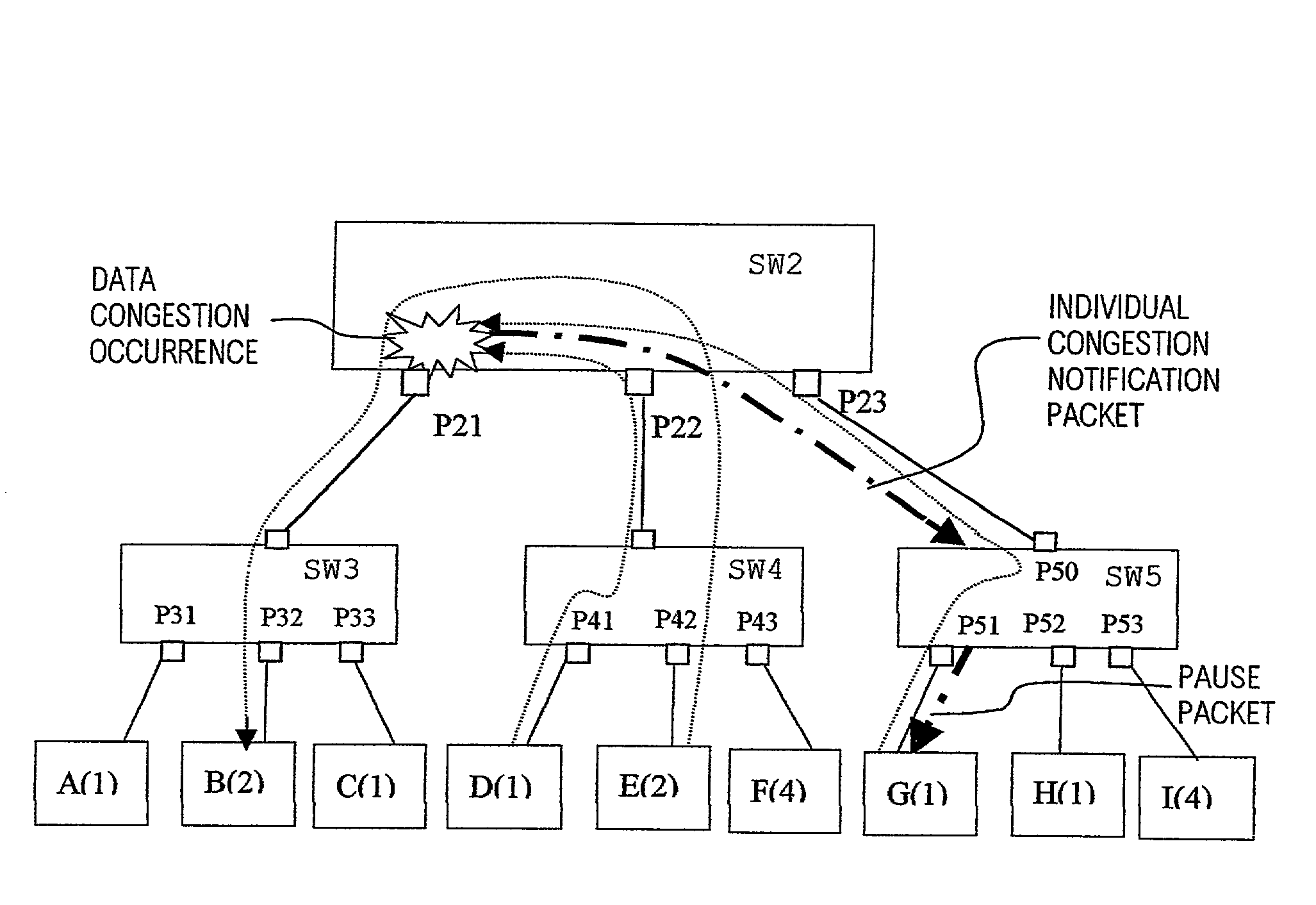
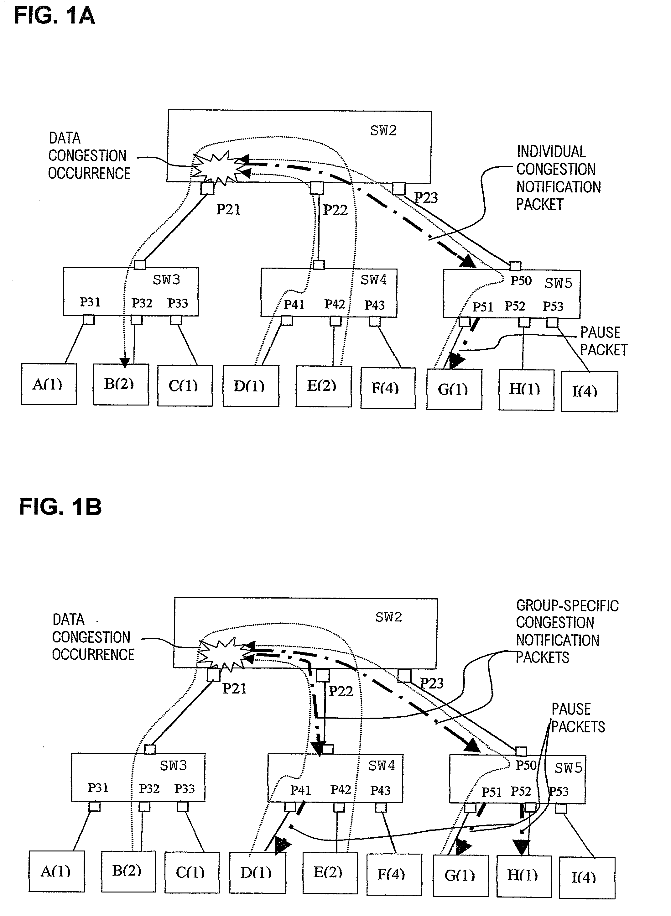
[0076] FIG. 1A is a diagram illustrating the general features of a flow control apparatus according to the present invention. The features of the embodiment can be summarized as follows:

[0077] (a) Data congestion judgement is applied, at each port of a switching hub, separately for respective terminal groups.

[0078] (b) Congestion notification packets are transmitted only to terminals of a group for which data congestion is judged to have occurred.

[0079] (c) Each port is provided with data output buffers respectively corresponding to the respective terminal groups, and congestion judgement is performed, at each port, based on the utilization levels of the buffers respectively corresponding to the various terminal groups (where "utilization level" signifies the amount of data currently held in a buffer) in relation to a predetermined threshold value of maximum utilization level.

[0080] (d) The congestion status of a port is judged in two stages, i.e., two successively increasing degree...

second embodiment

[0177] Second Embodiment

[0178] A second embodiment of the invention will be described referring to FIGS. 15 to 25. In the same way as for the preceding embodiments, the description applies to a port which handles data from a plurality of groups, unless otherwise indicated. The features of this second embodiment can be summarized as follows:

[0179] (a) Each port is provided with a single data output buffer, used in common by all terminal groups for which data packets can transmitted from the port (these being referred to in the following as "groups connected to the port").

[0180] (b) A threshold value of total data flow rate into the data output buffer is predetermined. Each time a received data packet is transferred to the buffer, a decision is made as to whether that threshold value has been exceeded. If so, that threshold value is divided by the total number of groups which are currently using the buffer, to obtain a flow rate threshold value that is allocated to each of these group...

third embodiment

[0220] Third Embodiment

[0221] A third embodiment will be described in the following, referring to FIGS. 26A to 32. The features of this embodiment can be summarized as follows:

[0222] (a) In each switching hub, congestion judgement for a port is performed separately various terminal groups, and a congestion notification packet is sent only to a group for which congestion is judged to have occurred.

[0223] (b) The congestion judgement is applied separately to respective ones of a plurality of buffers which are provided respectively assigned to the various terminal groups.

[0224] (c) Congestion status is judged in two stages, and flow control can be applied to individual ports or to pluralities of ports.

[0225] (d) When a congestion notification packet is received at a port of a switching hub, then congestion control is applied by halting readout from the data output buffer (of that receiving port) which corresponds to the terminal group specified in the congestion notification packet, an...


PUM


Abstract

In flow control apparatus formed of a network of switching hubs in a hierarchy configuration for performing data packet transfer within each of a plurality of respectively separate groups of terminals, based on use of group identifiers contained in the data packets, occurrence of congestion of the output section of a port of a switching hub is judged respectively separately for each of the terminal groups, and one or more congestion notification packets for effecting a pause in data packet transmission are generated and transmitted from that switching hub, directed only to one or more terminals of a group relating to the congestion. As a result, the effects of port congestion and of congestion control operations are limited to the terminal group concerned. Congestion can be judged for a terminal group based on a level of utilization of a port output buffer that is used only by that group, or based on a rate of flow of data from that group into a port output buffer which is used in common for all terminal groups, and congestion notification packets may be transmitted from a single port or from a plurality of ports of a switching hub, in accordance with the detected degree of congestion.

Description

[0001] This is a continuation-in-part application of Ser. No. 09 / 991843 filed Nov. 26, 2001, now abandoned.[0002] 1. Field of The Invention[0003] The present invention relates to a flow control apparatus and flow control method for data packets. In particular, the invention relates to a flow control apparatus within a data switching network formed of a plurality of switching hubs connected in a hierarchy and a plurality of terminal groups which are assigned respective group identifiers, with the data packets being transferred between the terminals via ports of the switching hubs, and with at least some of the ports utilizing the identifiers of respectively different groups for multiplexed operation.[0004] 2. Description of Prior Art[0005] The word "port" of a switching hub as used herein is to be understood to signify a port that is a combination of an input section and an output section, for respectively receiving and transmitting data packets. The term "terminal" is to be understo...

Claims


Application Information

Patent Timeline
Patent Type & Authority Applications(United States)
IPC IPC(8): H04L12/56
CPCH04L47/10H04L47/26
Inventor KAWAKAMI, TETSUYASUZUKI, YOSHIHIROKITAJIMA, SATOSHINAKAMURA, ATSUSHI
Owner PANASONIC CORP
Why Eureka
Try Eureka