Thrust plate assembly

a technology of thrust plate and assembly plate, which is applied in the direction of friction clutch, spring/damper, clutch, etc., can solve the problems of breaking the sam

Inactive Publication Date: 2002-12-05
ZF SACHS AG
View PDF11 Cites 5 Cited by
  • Summary
  • Abstract
  • Description
  • Claims
  • Application Information

AI Technical Summary

Problems solved by technology

While this compression loading is not a problem in conventional arrangements in which these tangential leaf springs are constructed essentially flat, i.e., without curvature, problems result in arrangements which are constructed...

Method used


Image

  • Thrust plate assembly
  • Thrust plate assembly
  • Thrust plate assembly

Examples


Embodiment Construction

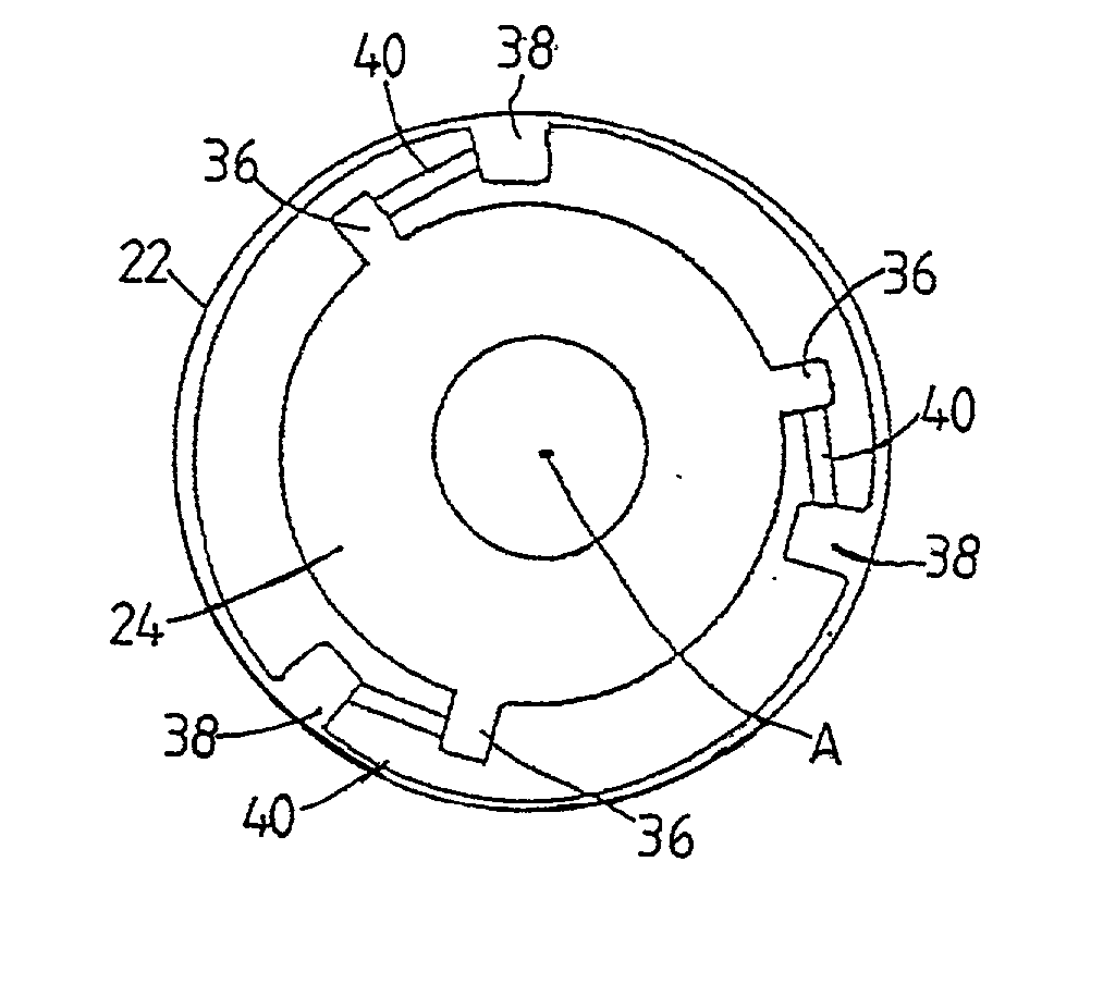
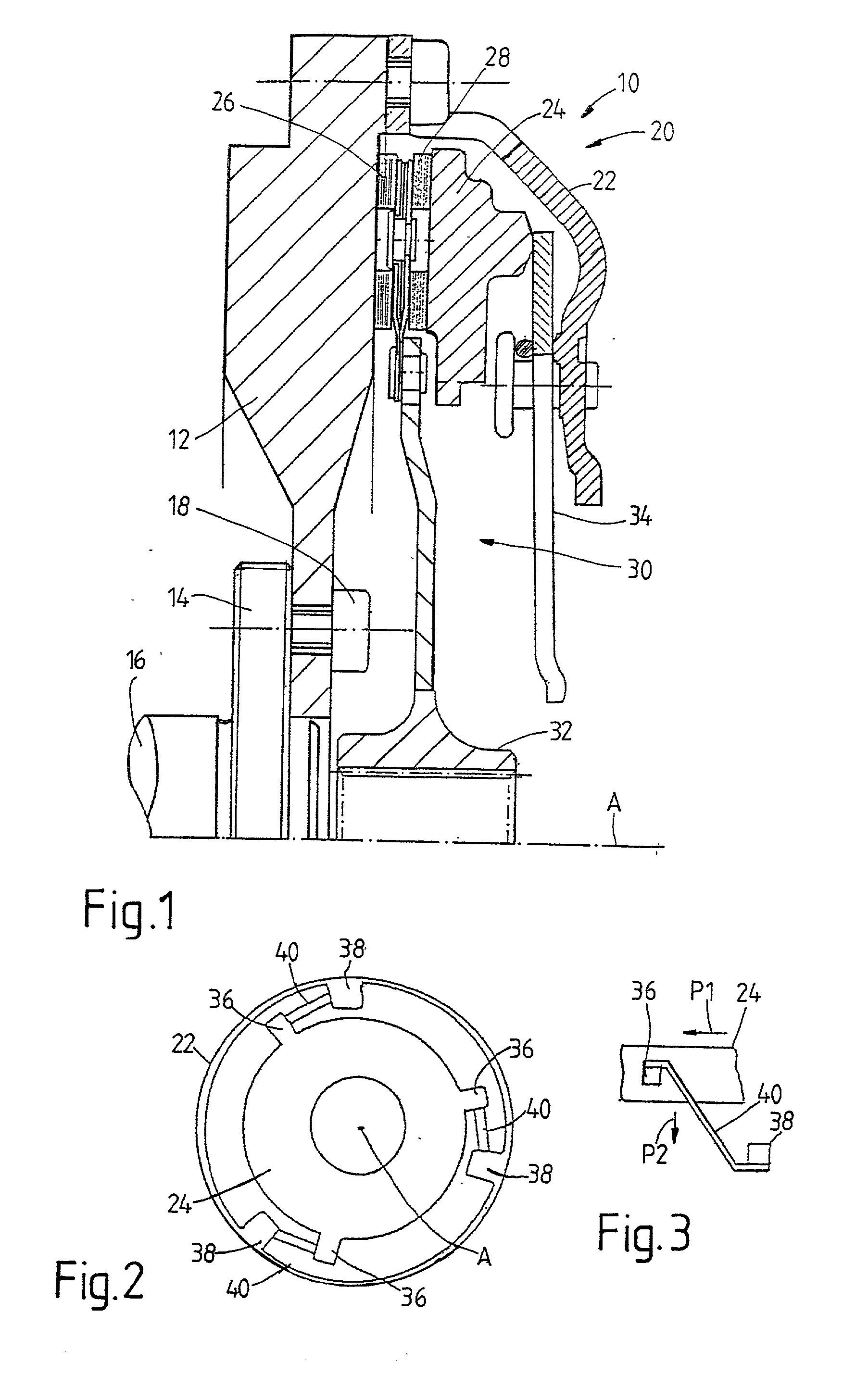
[0024] The basic construction of a friction clutch 10 in which the inventive principles are or can be realized is shown in FIGS. 1 and 2. The friction clutch 10 comprises a flywheel 12 which can be constructed, for example, as a dual-mass flywheel, which is secured in the radial inner area to a crankshaft flange 14 of a crankshaft 16 or some other drive shaft by a plurality of screw bolts 18. In its radial outer area, the flywheel 12 is fixedly connected with a thrust plate assembly 20. The thrust plate assembly 20 comprises a housing 22 and a pressure plate 24 which is axially displaceable in the housing 22 but is held so as to be substantially fixed with respect to rotation relative to the housing 22. The friction facings 26, 28 of a clutch disk 30 are located between the pressure plate 24 and the flywheel 12. This clutch disk 30 can be coupled in its radial inner hub area 32 with a driven shaft, for example, a transmission input shaft, so as to be fixed with respect to rotation r...


PUM


Abstract

A pressure plate is held by at least one leaf spring arrangement so as to be movable axially with respect to the housing. The at least one leaf spring arrangement cooperates in a first coupling area thereof with the pressure plate for transmission of force and cooperates in a second coupling area thereof with the housing for transmission of force. For this purpose, the at least one leaf spring arrangement cooperates in one of first coupling area and second coupling area with the component group of housing and pressure plate cooperating with this coupling area for transmission of force in order to transmit force in only one circumferential direction.

Description

[0001] 1. Field of the Invention[0002] The present invention is directed to a thrust plate assembly for a friction clutch, comprising a housing and a pressure plate which is held by at least one leaf spring arrangement so as to be movable axially with respect to the housing, and the at least one leaf spring arrangement cooperates in a first coupling area thereof with the pressure plate for transmission of force and cooperates in a second coupling area thereof with the housing for transmission of force.[0003] 2. Description of the Related Art[0004] Connecting a pressure plate to a housing arrangement by means of tangential leaf springs is a variant that has long been known in the area of friction clutches by which a pressure plate can be connected with the housing arrangement so as to be essentially fixed with respect to rotation and displaceable axially relative to this housing arrangement. In known friction clutches, the tangential leaf springs extend in circumferential direction p...

Claims


Application Information

Patent Timeline
IPC IPC(8): F16D13/71
CPCF16D2013/706F16D13/71
Inventor BACH, HARTMUTCARLSON, CORADORFLER, MATTHIASESLY, GUNTHERFELDHAUS, REINHARDHOFFELNER, INGRIDKLEUKER, CHRISTOPHKRAUS, PAULORLAMUNDER, ANDREASPEINEMANN, BERNDPETERSEIM, MICHAELROLL, GERHARDTILL, RALFVOGT, SEBASTIANDAU, ANDREAS
Owner ZF SACHS AG
Why Eureka
Try Eureka