Resilient mount for a CMC combustion of a turbomachine in a metal casing

a technology of metal casing and turbomachine, which is applied in the direction of machines/engines, mechanical equipment, light and heating apparatus, etc., can solve the problems of raw material cost, very different coefficients of thermal expansion of metal materials and composite materials, and the inability to use metal chambers completely. to achieve the effect of simplifying the manufacture of the combustion chamber and reducing the drawbacks

Inactive Publication Date: 2002-12-12
SN DETUDE & DE CONSTR DE MOTEURS DAVIATION S N E C M A
View PDF6 Cites 18 Cited by
  • Summary
  • Abstract
  • Description
  • Claims
  • Application Information

AI Technical Summary

Benefits of technology

0003] The present invention mitigates those drawbacks by proposing a mounting for the combustion chamber in the casing that has the ability to absorb the displacements induced...

Problems solved by technology

However, under certain particular conditions of use implementing very high combustion temperatures, using a metal chamber turns out to be completely unsuitable from a thermal point of view and it is necessary to make use of a chamber based on high temperature composite materials of the CMC type.
Unfortunately, the difficulties of working such materials and their raw material costs mean that use thereof is generally restricted to the combustion...

Method used


Image

  • Resilient mount for a CMC combustion of a turbomachine in a metal casing
  • Resilient mount for a CMC combustion of a turbomachine in a metal casing
  • Resilient mount for a CMC combustion of a turbomachine in a metal casing

Examples


first embodiment

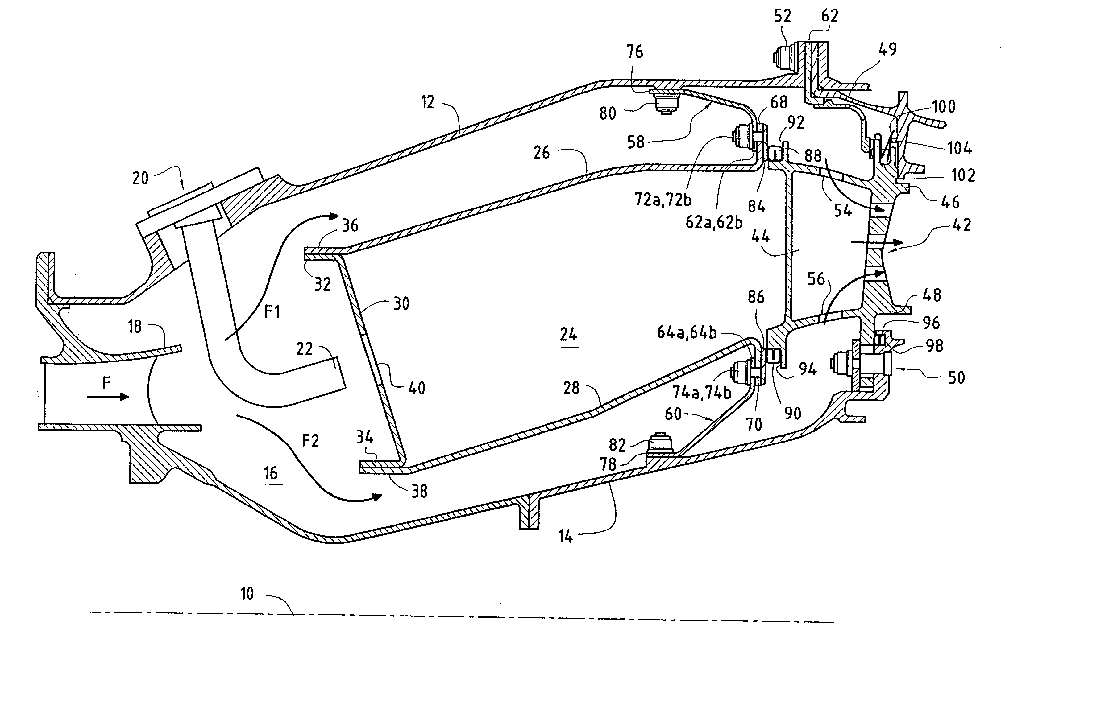
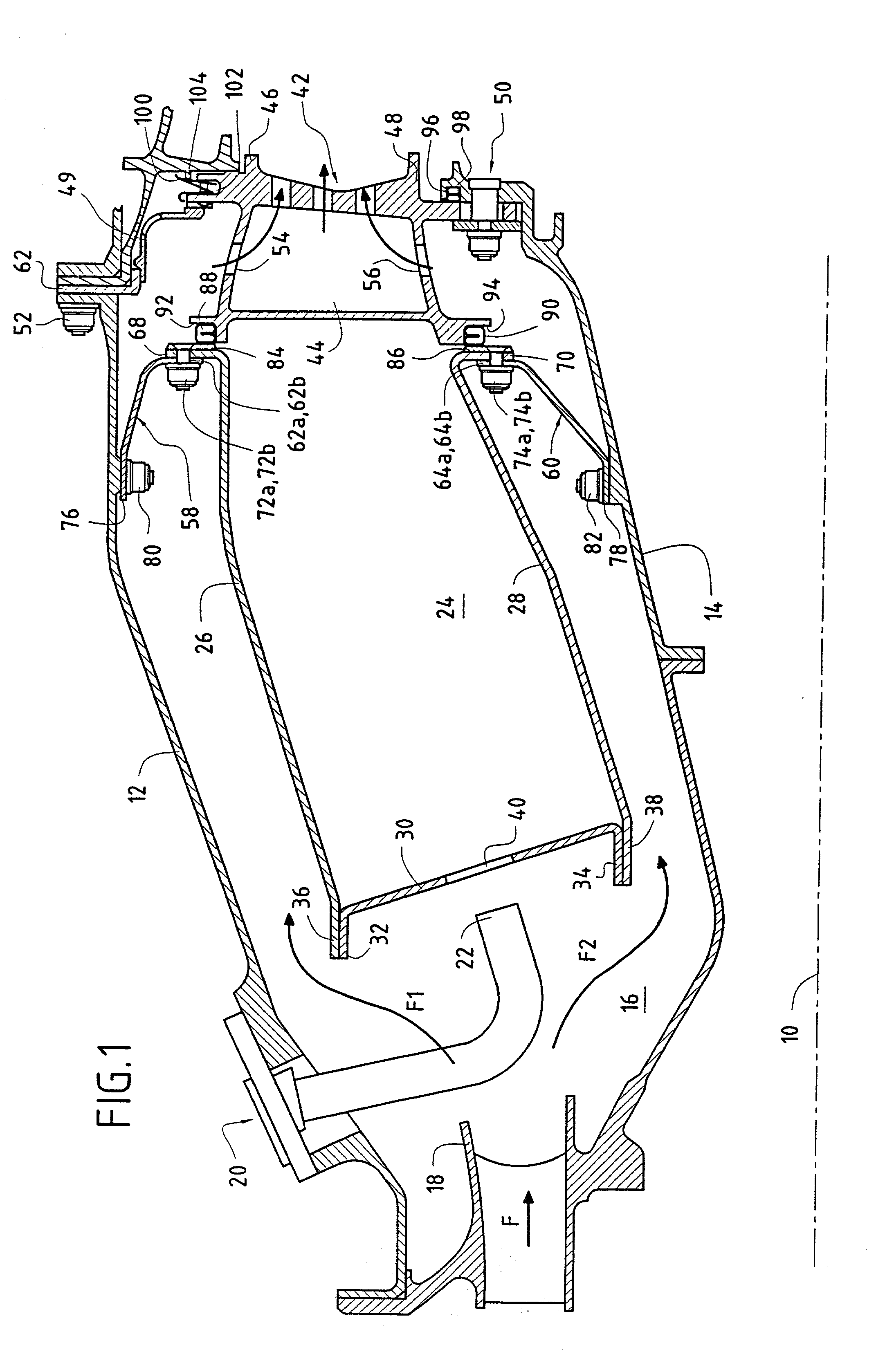
[0026] In the invention, the combustion chamber 24 which has a thermal expansion coefficient that is very different from that of the other parts making up the turbomachine, which parts are made of metal, is held securely in position inside the annular shell by a plurality of flexible tongues 58, 60 that are regularly distributed around the combustion chamber (FIG. 2 shows one such fixing). A first fraction of these fixing tongues (see tongue referenced 58) is fixed between the outer annular shell 12 and the outer side wall 26 of the combustion chamber, and a second fraction of these tongues (such as the tongue 60) is mounted between the inner annular shell 14 and the inner side wall 28 of the combustion chamber.

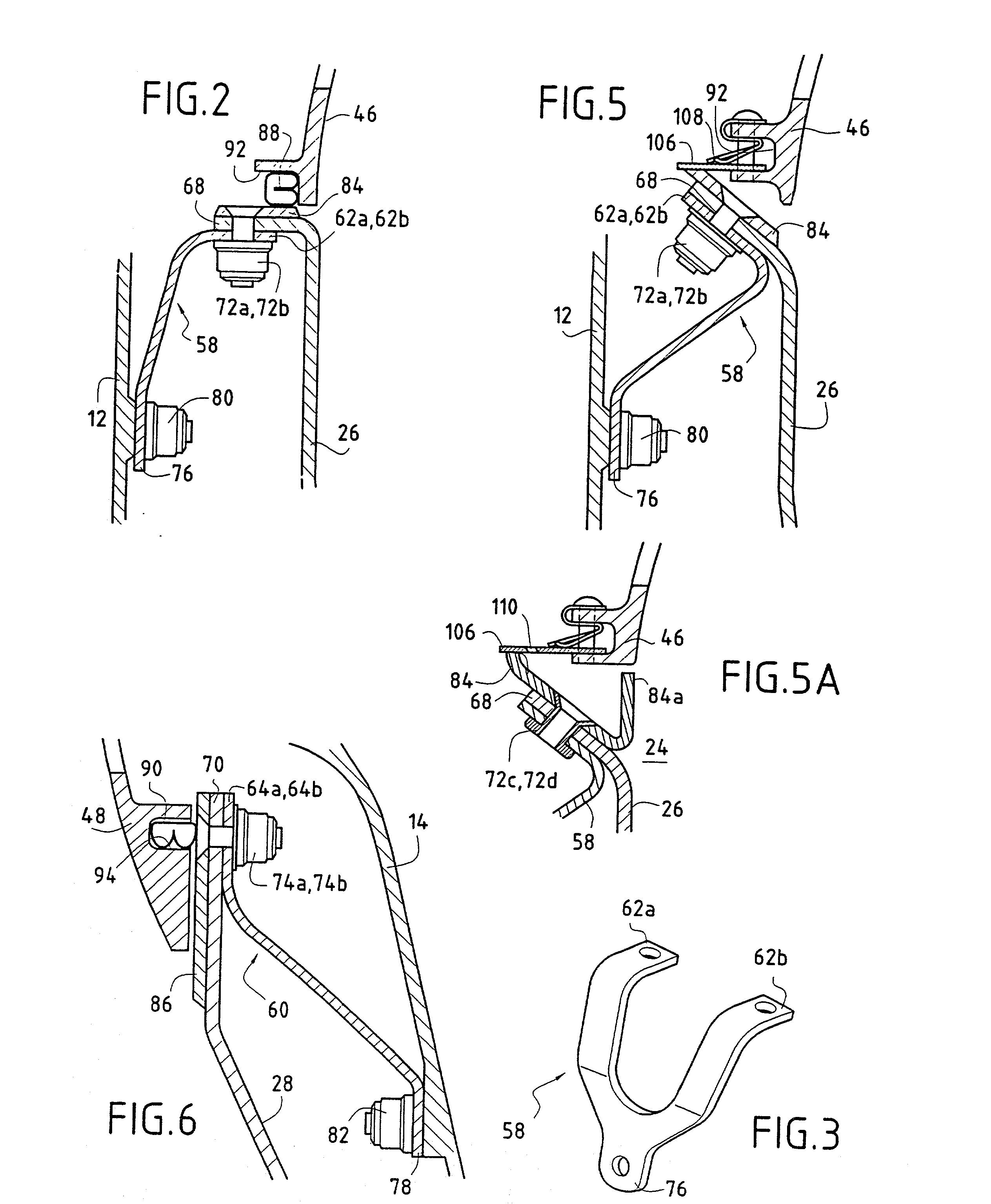
[0027] Each flexible fixing tongue of metal material, e.g. the tongue 58 shown in FIG. 3, comprises three branches connected together in a star configuration so as to be generally Y-shaped with three attachment points, with the ends 62a, 62b or 64a, 64b of two of these three ...

second embodiment

[0030] FIG. 4 shows the invention in which the downstream end of the combustion chamber no longer has a flange configuration perpendicular to the longitudinal axis of the combustion chamber, but on the contrary it has a configuration which is parallel to said axis or is inclined relative thereto (said inclination being at an angle that can be as much as 90.degree.). These non-perpendicular configurations for the downstream end of the combustion chamber make the side walls of the chamber easier to manufacture, in particular by enabling the material to be densified better in this region.

[0031] In the example shown, the downstream end 70 of the inner side wall 28 of the combustion chamber presents a configuration that is parallel to the longitudinal axis 10 of the chamber (see detail of FIG. 6) and bears radially via the composite material ring 86 against the inner circular platform 48 of the nozzle. As in the preceding version, this platform is provided with a groove 94 which receives...


PUM


Abstract

In a turbomachine comprising an annular shell of metal material containing in a gas flow direction F: a fuel injection assembly; an annular combustion chamber of composite material; and an annular nozzle of metal material forming the inlet stage with fixed blades of a high pressure turbine, provision is made for the combustion chamber to be held in position inside the annular metal shell by a plurality of flexible metal tongues each comprising three branches connected together in a star configuration, the ends of two of these three branches being fixed securely to a downstream end of the combustion chamber via respective first and second fixing means, and the end of the third branch being fixed securely to the annular shell via third fixing means.

Description

[0001] The present invention relates to the specific field of turbomachines and more particularly it relates to the problem posed by mounting a combustion chamber made of a ceramic matrix composite (CMC) type material in the metal casing of a turbomachine.PRIOR ART[0002] Conventionally, in a turbojet or a turboprop, the high pressure turbine (HPT) and in particular its inlet nozzle, the combustion chamber, and the casing (or "shell") of said chamber are all made of the same material, generally a metal. However, under certain particular conditions of use implementing very high combustion temperatures, using a metal chamber turns out to be completely unsuitable from a thermal point of view and it is necessary to make use of a chamber based on high temperature composite materials of the CMC type. Unfortunately, the difficulties of working such materials and their raw material costs mean that use thereof is generally restricted to the combustion chamber itself, while the high pressure t...

Claims


Application Information

Patent Timeline
IPC IPC(8): F02C7/00F02C7/20F23R3/00F23R3/42F23R3/60
CPCF05B2230/606F23R3/60F23R3/007
Inventor CAMY, PIERRECARRERE, BENOITCONETE, ERICFORESTIER, ALEXANDREHABAROU, GEORGESHERNANDEZ, DIDIER
Owner SN DETUDE & DE CONSTR DE MOTEURS DAVIATION S N E C M A
Why Eureka
Try Eureka