Intervertebral prosthesis

a technology of intervertebral prosthesis and hollow body, which is applied in the field of implants, can solve the problems of long-term risk of leakage proofing criteria of hollow body

Inactive Publication Date: 2003-01-23
ZIMMER GMBH
View PDF0 Cites 158 Cited by
  • Summary
  • Abstract
  • Description
  • Claims
  • Application Information

AI Technical Summary

Benefits of technology

[0007] This object is satisfied by an implant in accordance with the present invention, which comprises an elongated elastic body which is form-elastic and takes on the form of a spiral in the force-free state. The cross-section of the body is preferably rectangular, and the edges can also be rounded off. It is also possible to use bodies with a roundish cross-section as long as an essentially form-fitted, tilt-proof position of the spiral is retained under load. The cross-section of the elastic body need not be constant over its entire length, but rather it turns out that its thickness can preferably decrease in the outward direction. Such a spiral has the advantage that it winds itself, does not bend when thrust in, and can be severed at a suitable rolled-up length.
[0008] The implant as such can take the form of a cylindrical disc, i.e. can be made flat, or else can have inward and / or outward curvatures which follow the contours of the vertebral surfaces. In this way, the forces produced under load can be more uniformly distributed over the vertebral surfaces. The diameter of the spiral is preferably chosen such that the space within the annulus fibrosus is filled out.

Problems solved by technology

Furthermore, the leak-proofing criteria of the hollow body represent a long-term risk when the great stresses in the region of the vertebral column are taken into account.
Only small intervening spaces arise, which fill up with intervertebral fluid in the implanted state where present and which do not permit a canting of the elastic body under radial forces.

Method used


Image

  • Intervertebral prosthesis
  • Intervertebral prosthesis
  • Intervertebral prosthesis

Examples


Embodiment Construction

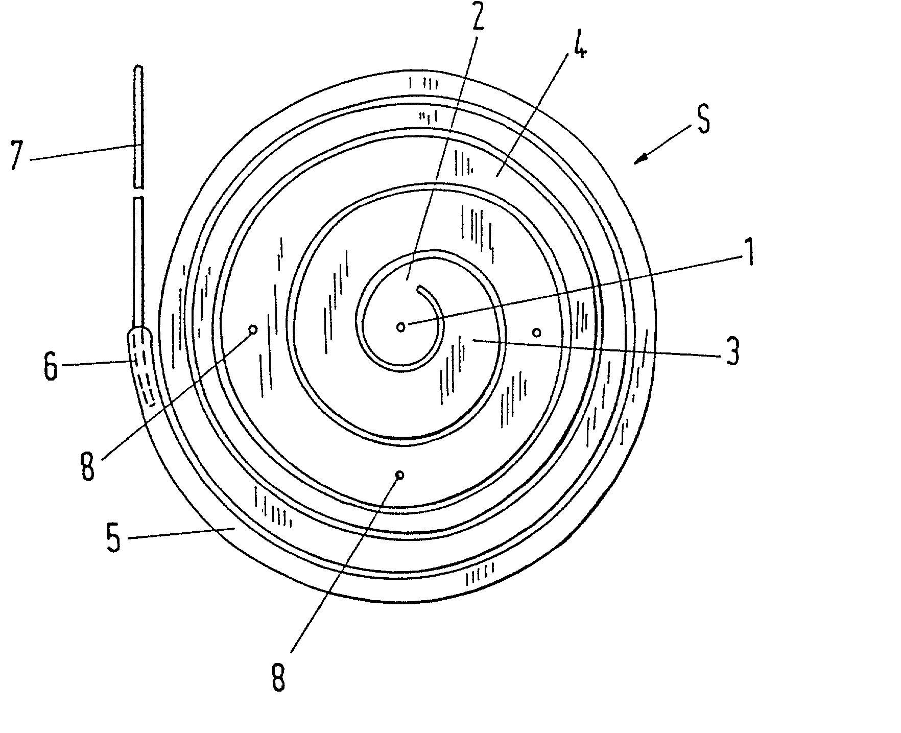
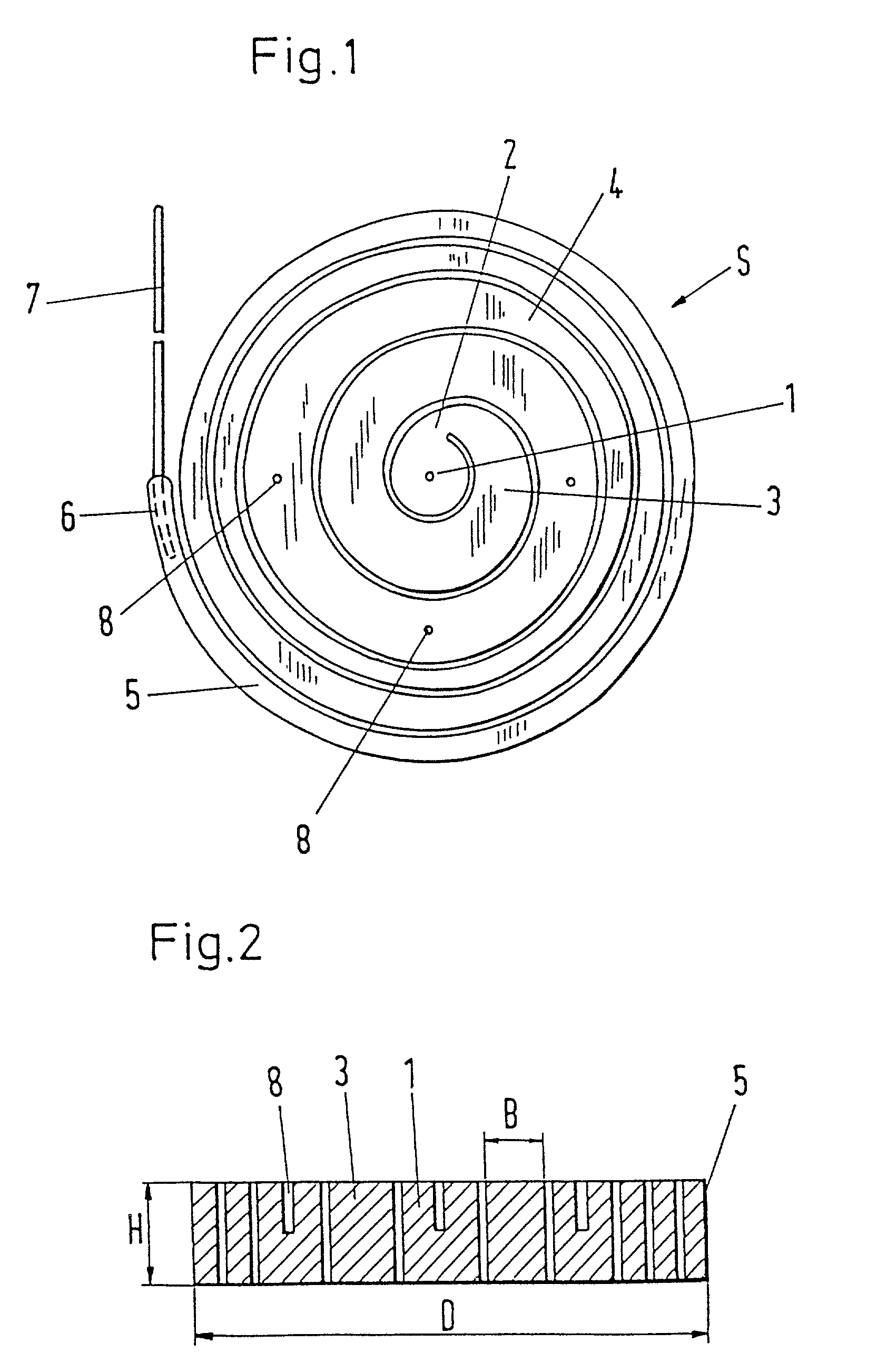
[0037] The figures deal with an implant, in particular an intervertebral prosthesis preferably of an elongated elastic body, which is form-elastic and takes on the form of a spiral S in the force-free state. The spiral can be drawn by reverse winding up into an insertion instrument, which is only insubstantially larger in the insertion region than the cross-section of the elongated elastic body in order to reach the inner space of an intervertebral disc through a small opening in the annulus fibrosus and to push in and separate off the self-winding spiral when the inner space is filled. This has the advantage that inner spaces of differing sizes can be filled with the same spiral.

[0038] FIG. 1 shows the spiral implant with a central middle part 1, which has essentially the form of a cylinder. This is joined at the side by a thin region 2 which permits a pronounced angular deflection and thus a form-fitted transition to the spiral turn 3 connected to it, essentially without interveni...


PUM


Abstract

The invention deals with an implant, in particular, an intervertebral prosthesis, which consists of an elongated elastic body which is form-elastic and takes on the form of a spiral S in the force-free state. The spiral can be drawn by a reverse winding up into an insertion instrument which is only unsubstantially larger in the insertion region than the cross-section of the elongated elastic body in order to reach the inner space of an intervertebral disc through a small opening in the annulus fibrosus and to push in and sever off the self-winding spiral when the interior is filled. This has the advantage that inner spaces of differing sizes can be filled with the same spiral.

Description

CROSS-REFERENCES TO RELATED APPLICATIONS[0001] This application is a continuation-in-part application and claims priority from U.S. patent application Ser. No. 09 / 249,945 filed Feb. 12, 1999; and U.S. patent application Ser. No. 09 / 249,934 filed Feb. 12, 1999 both of which are divisional applications and claim priority from U.S. patent application Ser. No. 08 / 723,146, filed Sep. 30, 1996; the disclosures of which are incorporated herein by reference.[0002] 1. Field of the Invention[0003] The invention relates to an implant, in particular an intervertebral prosthesis, consisting of an elongated elastic body.[0004] 2. Description of the Prior Art[0005] A prosthesis of this type is known from EP-A-O 453 393. It serves as replacement for a damaged intervertebral disc nucleus (nucleus pulposus). The outer ring (annulus fibrosus) of a natural intervertebral disc remains intact for the most part. The known prosthesis consists of a fluid-tight hollow body which is filled with an incompressi...

Claims


Application Information

Patent Timeline
Patent Type & Authority Applications(United States)
IPC IPC(8): A61B17/56A61B17/00A61B17/32A61F2/00A61F2/30A61F2/44A61F2/46
CPCA61B17/3201A61B2017/00469A61F2/442A61F2/4611A61F2002/3008A61F2002/30225A61F2002/30293A61F2002/30573A61F2002/4415A61F2002/444A61F2002/4622A61F2002/4627A61F2002/4628A61F2230/0069A61F2230/0091A61F2250/0098A61F2310/00023Y10S606/907Y10S606/91
Inventor HUSSON, JEAN-LOUIS
Owner ZIMMER GMBH
Why Eureka
Try Eureka