Airbag

a technology of airbags and airbags, applied in the field of airbags, can solve the problems of poor gas efficiency and passenger crash onto the airbag, and achieve the effect of improving airbag safety and reducing airbag impa

Inactive Publication Date: 2003-01-30
TAKATA CORPORATION
View PDF8 Cites 20 Cited by
  • Summary
  • Abstract
  • Description
  • Claims
  • Application Information

AI Technical Summary

Benefits of technology

0014] The airbag according to the present invention may further include at least one through port or hole for allowing the first and third compartments to communicate with each other. This configuration makes the third compartment inflate early.
0015] The airbag according to the present invention may further include at least one vent hole. A compartment into which the gas flows last communicates with an outside of the airbag through the vent hole. This vent hole absorbs a shock when a passenger crashes onto the airbag. However, it is possible that the passenger may crash onto the airbag before the last compartment is fully inflated. In such a case, since the gas discharging from the second compartment to the third compartment can absorb an impact, the airbag without a vent hole can sufficiently absorb the impact.

Problems solved by technology

Since the above-described airbag with the two compartments has a relatively large volume, the inflator, i.e. gas generator, is required to have a large capacity to inflate a peripheral portion of the airbag quickly, resulting in relatively poor gas efficiency.
However, it is possible that the passenger may crash onto the airbag before the last compartment is fully inflated.

Method used


Image

  • Airbag
  • Airbag
  • Airbag

Examples


Embodiment Construction

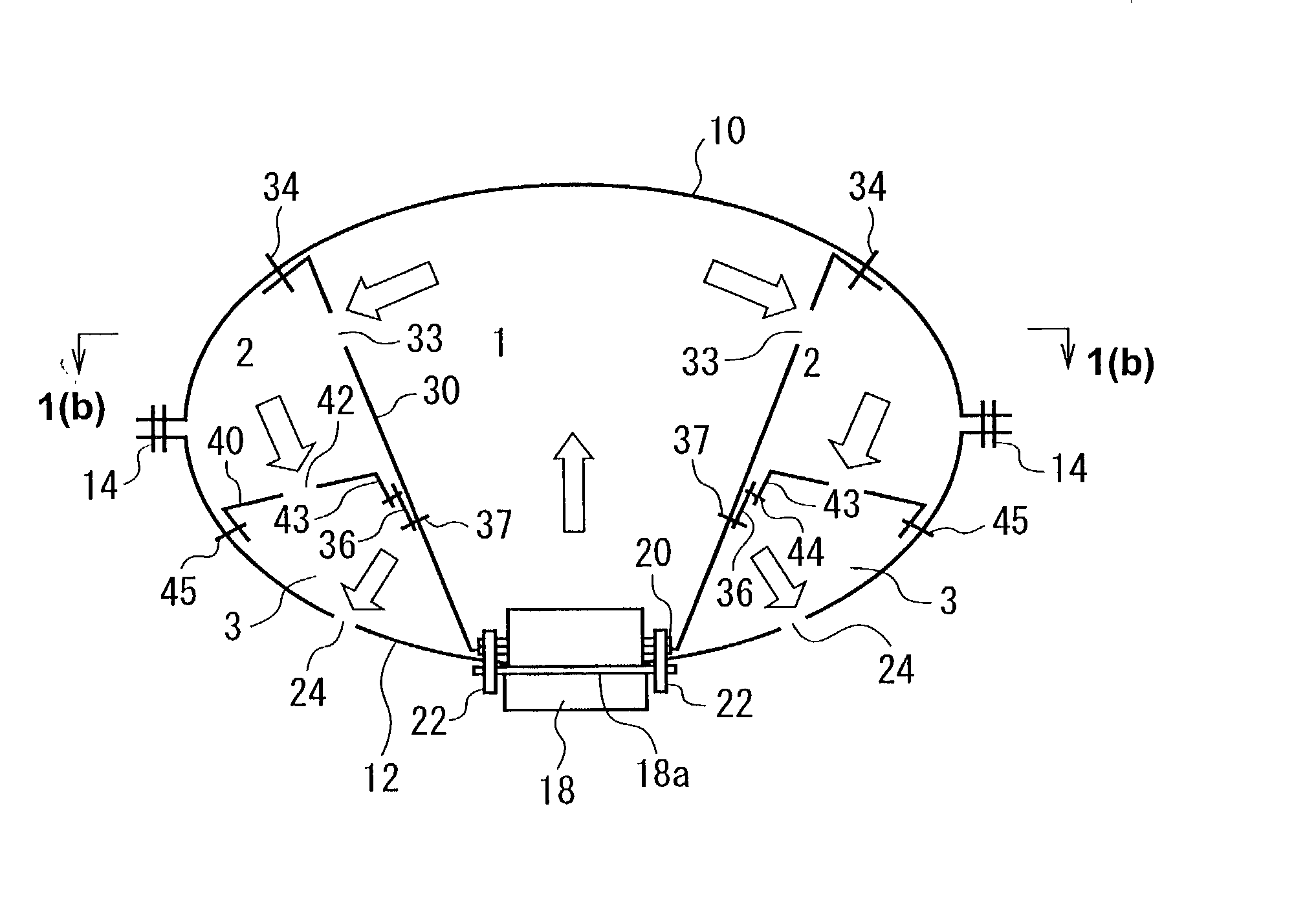
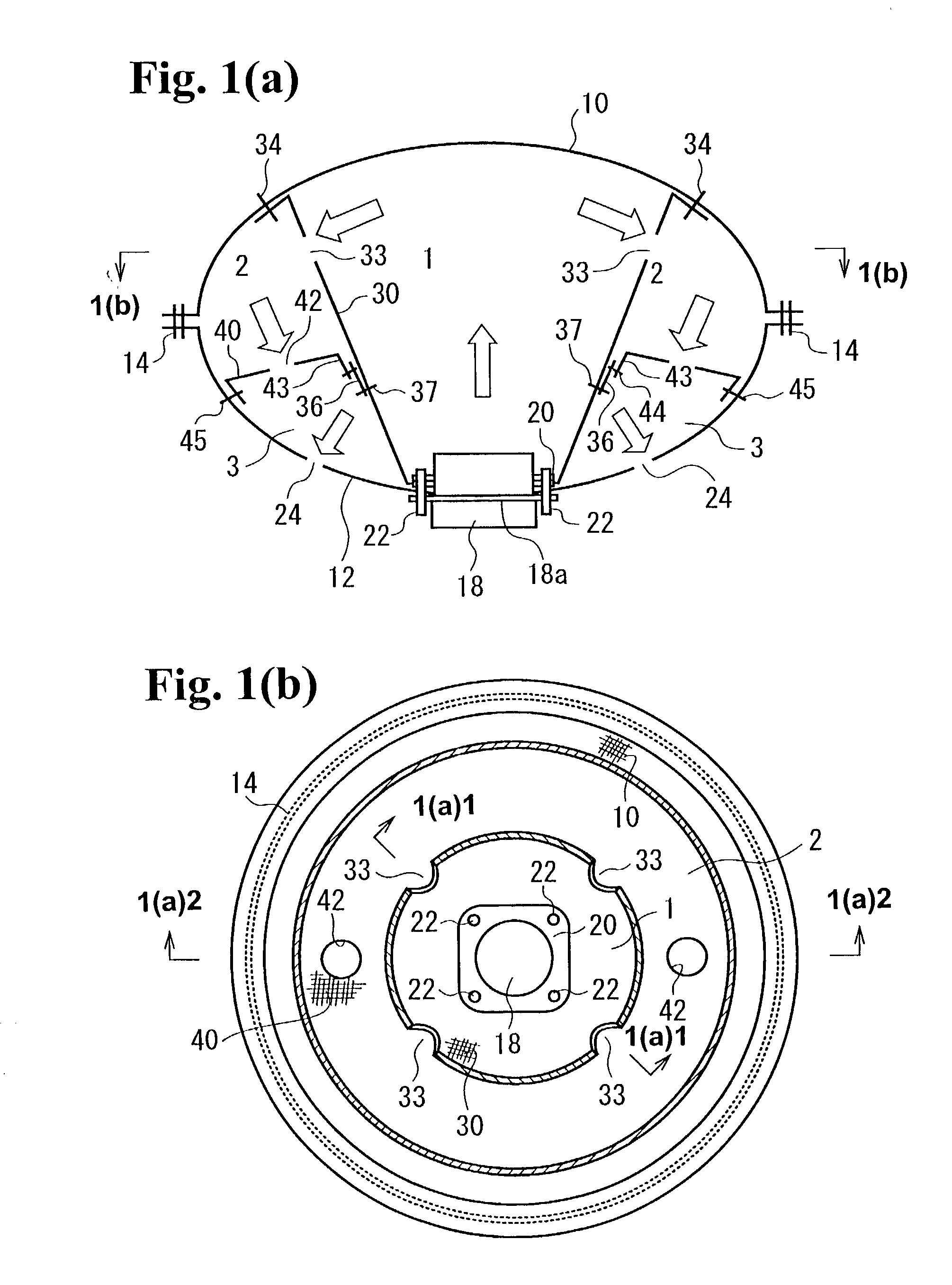
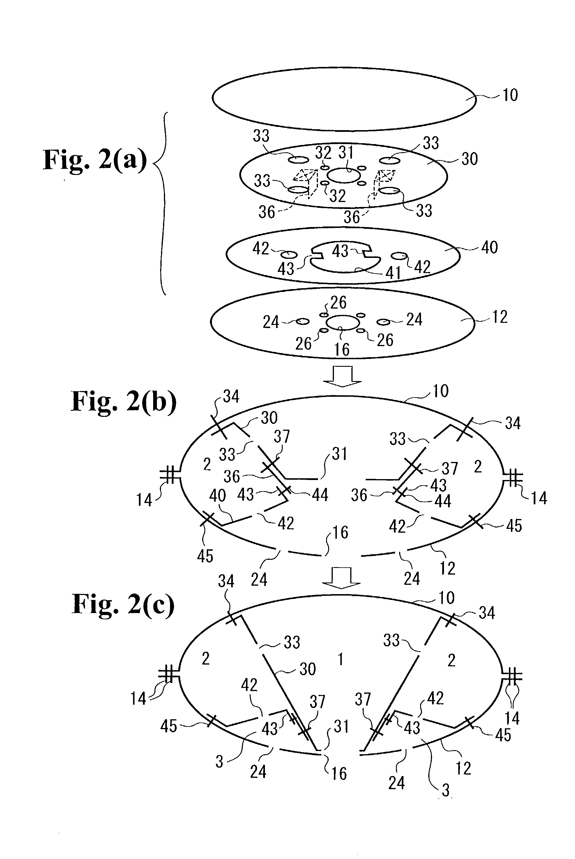
[0023] Hereunder, embodiments of the present invention will be explained with reference to the accompanied drawings. FIG. 1(a) is a longitudinal sectional view of an inflated airbag according to an embodiment, and FIG. 1(b) is a sectional view Laken along a line 1(b)-1(b) in FIG. 1(a). FIG. 2(a) is an exploded perspective view illustrating a configuration of an airbag, and FIGS. 2(b) and 2(c) are sectional views of the same.

[0024] An upper half of FIG. 1(a) is a sectional view taken along a line 1(a)1-1(a)1, and a lower half of FIG. 1(a) is a sectional view taken along a line 1(a)2-1(a)2 in FIG. 1(b), respectively.

[0025] The airbag has an outer shell formed of a round front panel 10 and a round rear panel 12. The front panel 10 and the rear panel 12 are stitched together with a suture thread 14 at an outside periphery thereof so as to form a bag. The rear panel 12 has an opening 16 in a central part thereof for receiving an inflator 18. The rear panel 12 also has a plurality of smal...


PUM


Abstract

An airbag is formed by an outer panel member for constituting the bag having a front side and a rear side with an opening for receiving gas to be inflated. The airbag includes at least three compartments arranged inside the bag including a first compartment communicating with the opening, a second compartment situated adjacent to the first compartment, and a third compartment situated adjacent to the second compartment. The gas flows from the first compartment to the third compartment through the second compartment.

Description

BACKGROUND OF THE INVENTION AND RELATED ART STATEMENT[0001] The present invention relates to an airbag for protecting a passenger in an emergency, such as a car crash, and more specifically, relates to an airbag suitable for a driver-side airbag installed in a steering device.[0002] In a driver-side airbag apparatus, an airbag folded and housed in a retainer has been widely used, and a cover member, such as a module cover, covers the airbag. When a sensor detects a car crash, an inflator is activated, and generates gas (inflation gas) to inflate the airbag.[0003] In Japanese Patent Publications (KOKAI) No. 01-247242 and No. 05-155300, a driver-side airbag having two compartments, namely a central compartment and a peripheral compartment, is disclosed. A partitioning panel divides inside of the airbag to form the two compartments, and the central compartment inflates first followed by the peripheral compartment. The partitioning panel has through ports or holes for the gas to flow ou...

Claims


Application Information

Patent Timeline
Patent Type & Authority Applications(United States)
IPC IPC(8): B60R21/16B60R21/233B60R21/235
CPCB60R21/233B60R2021/23324B60R2021/23538
Inventor ABE, KAZUHIROGU, WEIXIN
Owner TAKATA CORPORATION
Why Eureka
Try Eureka