Roughened coatings for gas turbine engine components

a gas turbine engine and coating technology, applied in the field of coating metal components, can solve the problems of limited improvement in aerodynamic efficiency and complex manufacturing process of components, and achieve the effects of improving the aerodynamic efficiency of gas turbine engine components, slowing down airflow velocity, and increasing surface roughness

Active Publication Date: 2012-03-20
AEROMET TECH
View PDF13 Cites 14 Cited by
  • Summary
  • Abstract
  • Description
  • Claims
  • Application Information

AI Technical Summary

Benefits of technology

[0010]The surface finish of the present invention deviates from conventional turbine blade designs that specify the turbine blades to be as smooth as possible to contribute to laminar flow and to optimize the flow of hot exhaust gases beneath the concave portion of the airflow surface of the turbine blade. Typically, a desired surface roughness (RA) for the surface finishes of the convex and concave portions of the airflow surface is less than about 68 microinches, after aluminiding. In contrast, the present invention advantageously applies an aluminide coating to the convex airflow surface portion that increases the surface roughness above this conventional desired value. The concave airflow surface portion may have a conventional surface roughness but, in any event, has a smoother surface than all or part of the convex airflow surface portion. The difference in surface roughness slows the airflow velocity across the convex airflow surface portion in comparison to the airflow velocity across the concave airflow surface portion.
[0011]The present invention improves the aerodynamic efficiency of gas turbine engine components providing aerodynamic lift without the need for complex component geometries and / or improves the aerodynamic lift in components having complex geometries beyond the gains provided solely by the geometry.

Problems solved by technology

However, these conventional approaches that focus solely upon advances in component geometry introduce complexity into the component manufacture process and are ultimately limited in the improvement in aerodynamic efficiency.

Method used


Image

  • Roughened coatings for gas turbine engine components
  • Roughened coatings for gas turbine engine components
  • Roughened coatings for gas turbine engine components

Examples


Embodiment Construction

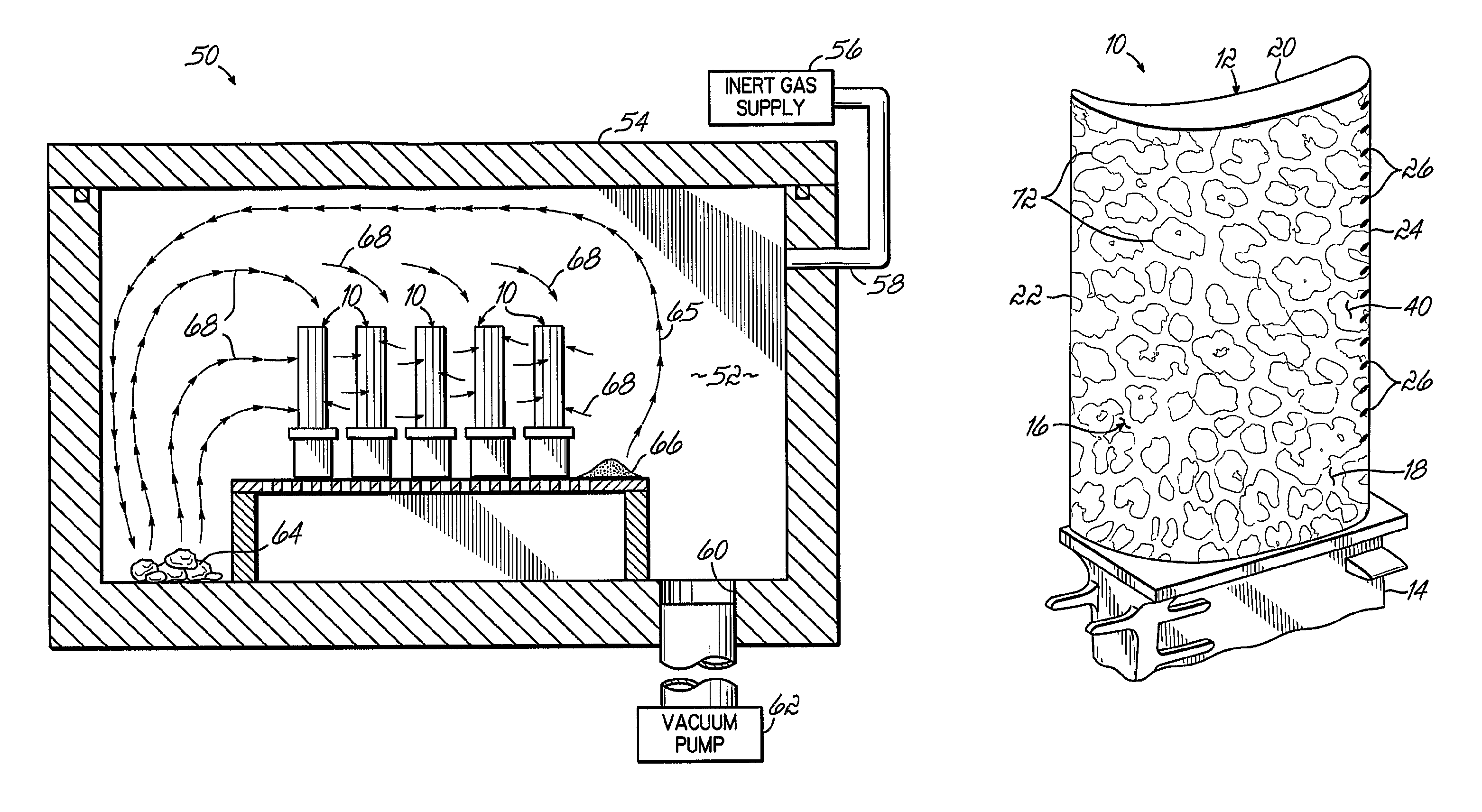
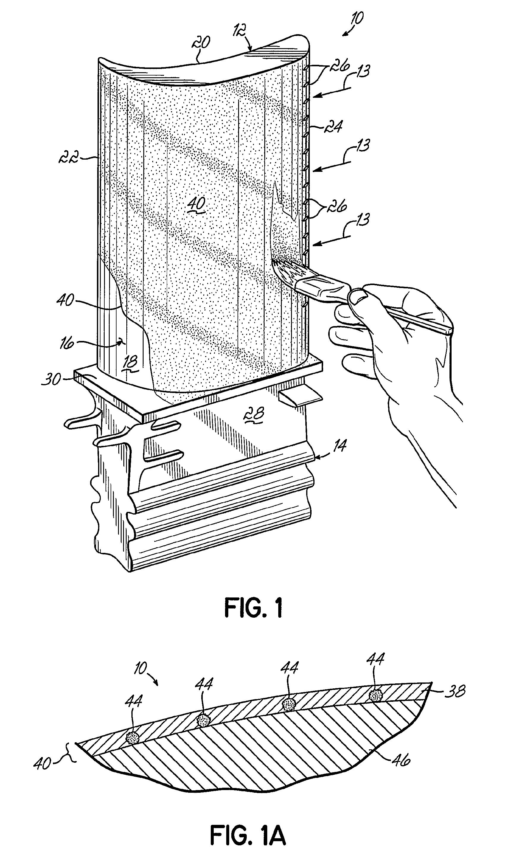
[0020]With reference to FIG. 1 and in accordance with the principles of the present invention, a gas turbine engine component 10, in a representative construction, includes an airfoil segment 12 designed to be in the high-pressure, hot airflow path (as indicated by arrows 13). Integral with airfoil segment 12 is a root 14 used to secure gas turbine engine component 10 to the turbine disk (not shown) of the gas turbine engine (not shown). The airfoil segment 12 is fabricated from any suitable nickel-, cobalt-, or iron-based high temperature superalloy from which such gas turbine engine components 10 are commonly made. The base element, typically nickel or cobalt, is by weight the single greatest element in the superalloy. For example, where the component 10 is a gas turbine component in a jet engine, segment 12 may be the nickel-based superalloy Inconel 795 Mod 5A or CMSX-4. The present invention is, however, not intended to be limited to any particular gas turbine engine component 1...


PUM

PropertyMeasurementUnit
temperatureaaaaaaaaaa
operating temperaturesaaaaaaaaaa
operating temperatureaaaaaaaaaa

Abstract

A gas turbine engine component (10) with an aluminide coating (42) on at least a portion of an airflow surface (18) that includes a roughening agent (44) effective to provide a desired surface roughness and a deposition process for forming such aluminide coatings (42). A layer (40) including a binder (38) and the roughening agent (44) maybe applied to the superalloy substrate (46) of the component (10) and the aluminide coating (42) formed on the airflow surface portion by exposing the component (10) and layer (40) to an appropriate deposition environment. Suitable roughening agents include metal and ceramic particles (44) that are dispersed on the airflow surface portion before exposure to the deposition environment. The particles (44), which are substantially intact after the aluminide coating (42) is formed, are dispersed in an effective number to supply the desired surface roughness.

Description

FIELD OF THE INVENTION[0001]The present invention relates to coated metal components and, more particularly, gas turbine engine components with a roughened coating and methods of forming such roughened coatings on gas turbine engine components.BACKGROUND OF THE INVENTION[0002]Intermetallic layers and coatings are often formed on a surface of a metal component to protect the underlying metal substrate of the component and to extend its useful life during operation. For example, many superalloy components in gas turbine engines, like turbine blades, vanes, and nozzle guides, include an aluminide coating on airflow surfaces that protects the underlying superalloy base metal from high temperature oxidation and corrosion. Among other applications, gas turbine engines are used as aircraft or jet engines, such as turbofans. Gas turbine engines are also used in electromotive power generation equipment, such as industrial gas turbine engines, to generate electricity, and as power plants prov...

Claims


Application Information

Patent Timeline
Patent Type & Authority Patents(United States)
IPC IPC(8): B32B15/16F01D5/14
CPCF01D5/288Y02T50/67Y02T50/671Y02T50/673F05D2300/21F05D2230/90Y10T428/12535F05D2300/611F05D2300/614F05D2250/28F05D2230/31Y10T428/12736Y10T428/12993F05D2250/61Y02T50/60
Inventor FAIRBOURN, DAVID C.
Owner AEROMET TECH
Why Eureka
Try Eureka