
Paintball gun with rearwardly removable pneumatic assembly

Inactive Publication Date: 2009-04-16
SMART PARTS
View PDF15 Cites 11 Cited by
  • Summary
  • Abstract
  • Description
  • Claims
  • Application Information

AI Technical Summary

Benefits of technology

[0008]The bolt preferably includes a forward and a rearward piston surface area. A quantity of compressed gas is preferably selectively supplied and vented from a forward piston surface area through a mechanical or electro-pneumatic valving mechanism. The firing mechanism preferably consists of a sealing member arranged in selective communication with an outer surface of the bolt. One or more firing ports are preferably arranged in the bolt to communicate compressed gas through the bolt to launch a paintball. Compressed gas from the regulator can be supplied to the compressed gas storage area through a supply port. The flow of compressed gas into the compressed gas storage area can be restricted or prevented during a firing operation to increase gas efficiency of the paintball gun.
[0011]When the bolt transitions to its forward position, a sealing member of the firing mechanism preferably disengages from the bolt surface area, permitting compressed gas from the compressed gas storage area to enter the bolt firing ports and launch a paintball from the marker. In addition, with the bolt in the firing position, the flow of compressed gas into the compressed gas storage area can be restricted. This can be accomplished, for instance, by configuring a rearward portion of the bolt to reduce the area through which compressed gas travels from the supply port to the compressed gas storage area. Alternatively, the supply of compressed gas to the compressed gas storage chamber can be cut off completely to prevent compressed gas from entering the storage chamber during the firing operation. This can be accomplished, for instance, by closing off the gas supply port using sealing members on a rearward end of the bolt, using sealing members on a separate, independent piston, by pinching a gas supply tube, or using a separate valving mechanism.

Problems solved by technology

At high rates of fire, even when electronic sensors and other sophisticated equipment are used to prevent ball breaks in the breech of the paintball gun, ball breaks may occasionally occur.
The internal paintball gun chambers and components may also need routine maintenance and / or lubrication.
Although quick-removal bolt assemblies, such as that shown in U.S. Pat. No. 7,237,544, have been provided for a number of years for stacked-tube design paintball guns, quick removal solutions for single-bore or spool-valve designs have been more complicated to provide.

Method used


Image

  • Paintball gun with rearwardly removable pneumatic assembly
  • Paintball gun with rearwardly removable pneumatic assembly
  • Paintball gun with rearwardly removable pneumatic assembly

Examples


Embodiment Construction

[0036]Various preferred aspects of the present invention will now be described in detail with reference to the accompanying figures. It should be noted, however, that the following description is provided by way of example only and not of limitation, and that many other implementations and embodiments of the present invention will be readily apparent to those skilled in the art based on the disclosure herein. The scope of the invention is therefore not limited to the particular embodiments described herein.

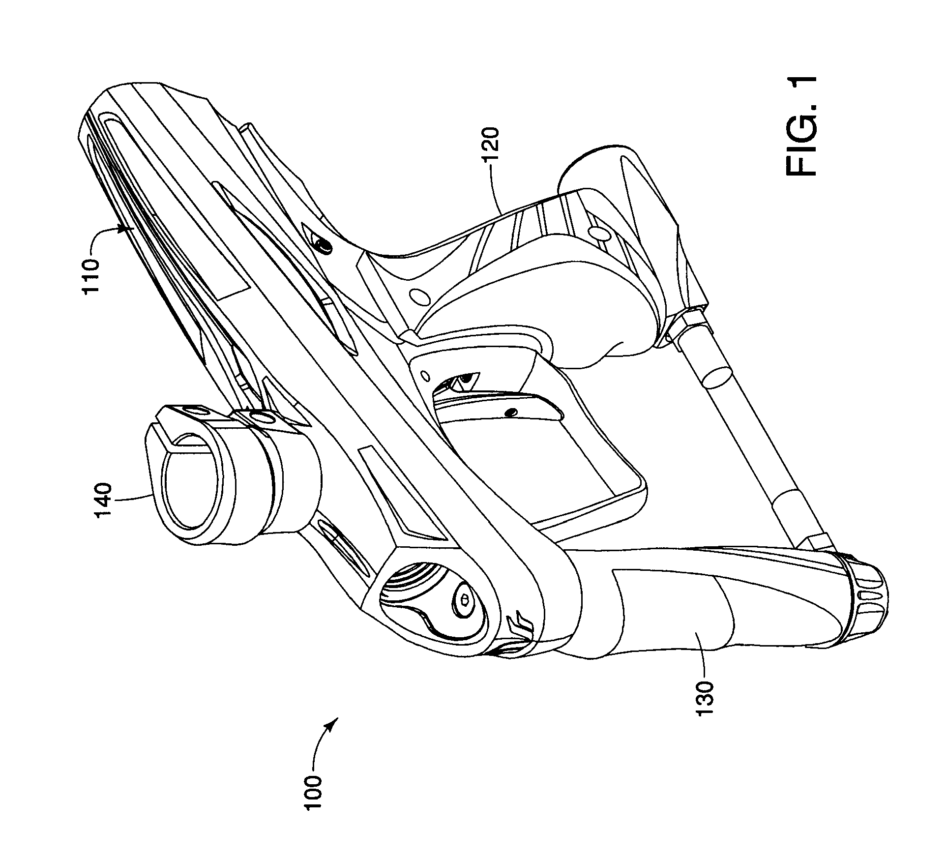
[0037]FIG. 1 is a somewhat schematic perspective view of a paintball gun 100 having a rearwardly removable pneumatic assembly according to principles of the present invention. Referring to FIG. 1, the paintball gun 100 includes a body 110 having a grip frame 120 and receiving a pneumatic regulator 130 and a feedneck 140. The body 110 is also configured to receive a barrel (not shown) into the breech of the paintball gun 100.

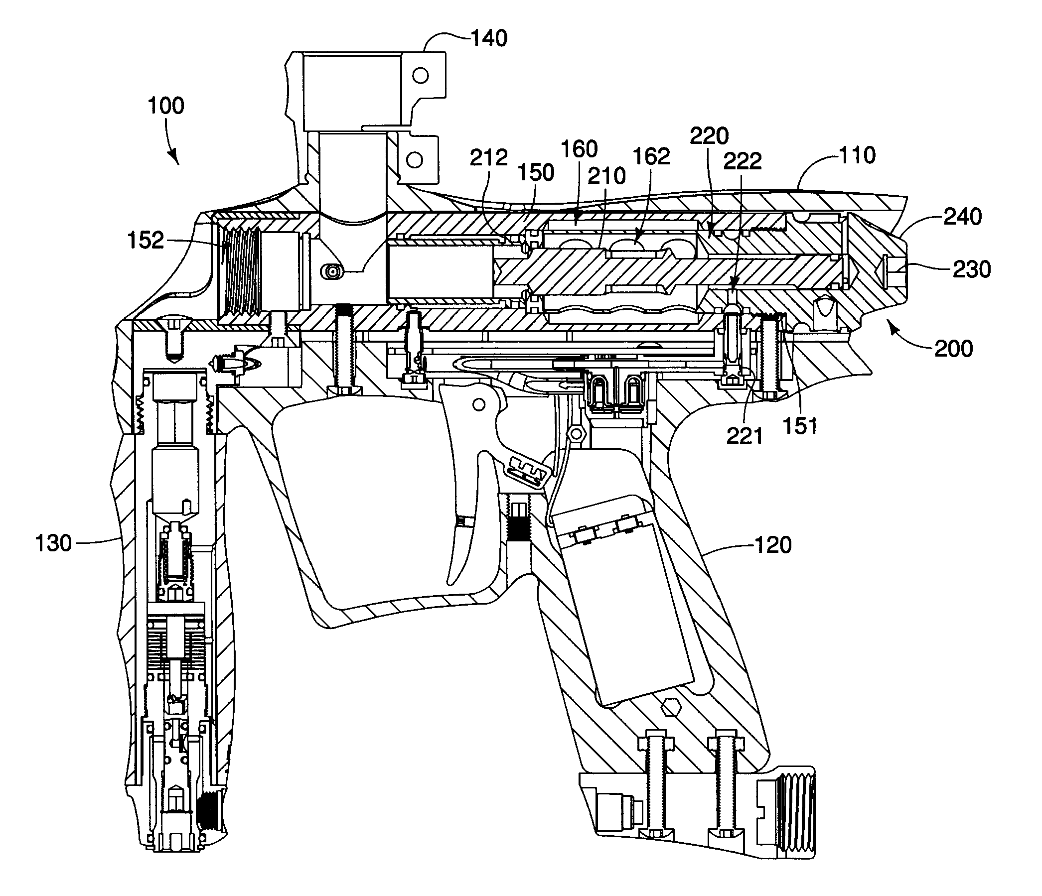
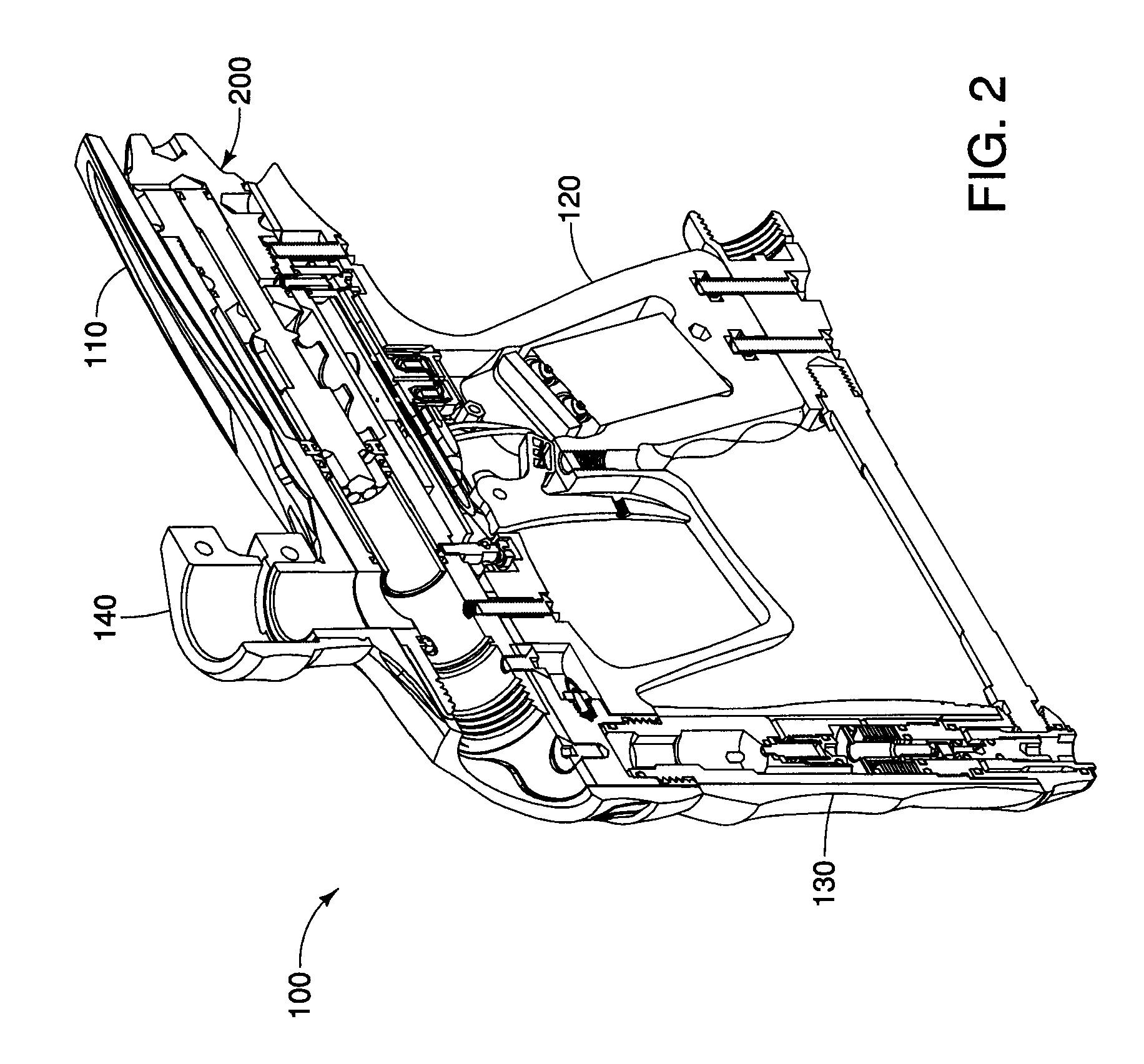
[0038]FIGS. 2 and 3 are somewhat schematic cross-sectiona...


PUM


Abstract

A paintball gun having a rearwardly removable pneumatic assembly is provided. The pneumatic assembly preferably comprises a bolt and a bolt housing. A pneumatic cylinder is preferably arranged within a body of the paintball gun to receive the pneumatic assembly. A rearward opening is preferably provided in the body to provide access to the pneumatic cylinder for positioning and removal of the pneumatic assembly. The pneumatic assembly can be configured for removal with or without tools. In one embodiment, a cover plate can also be provided to cover the rearward opening in the body and prevent access to the pneumatic assembly until the cover plate is removed. A solenoid valve assembly is also provided having an upper and lower body section connected together through a tab and detent structure.

Description

[0001]This application claims priority from Provisional U.S. Patent Application Ser. Nos. 60 / 979,754 filed Oct. 12, 2007 and 60 / 981,299 filed Oct. 19, 2007, the contents of which are incorporated herein by reference in their entirety.BACKGROUND OF THE INVENTION[0002]1. Field of the Invention[0003]This invention relates generally to pneumatic paintball guns (“markers”) and their operating components. More particularly, this invention relates to a pneumatic paintball gun that permits rearward removal of the pneumatic components of the paintball gun.[0004]2. Related Art[0005]Modern paintball guns are generally capable of operating at high rates of fire. At high rates of fire, even when electronic sensors and other sophisticated equipment are used to prevent ball breaks in the breech of the paintball gun, ball breaks may occasionally occur. The internal paintball gun chambers and components may also need routine maintenance and / or lubrication. When a ball breaks in the breech of the pai...

Claims


Application Information

Patent Timeline
IPC IPC(8): F41B11/00F41B11/32
CPCF41B11/721
Inventor JONES, DANIAL S.
Owner SMART PARTS
Learn More